These sample Mission Plans cover various aspects of performing maneuvers in FreeFlyer. After exploring these Mission Plans, continue to the Maneuvering Guide for more information.
Jump to a Mission Plan Description:
Mission Plan |
Engineer |
Mission |
• |
• |
|
• |
• |
|
• |
• |
|
• |
• |
|
• |
• |
|
• |
• |
|
• |
• |
|
• |
• |
|
• |
• |
|
• |
• |
|
• |
• |
|
• |
• |
|
• |
• |
|
• |
• |
|
• |
• |
|
|
• |
|
• |
• |
|
• |
• |
|
• |
• |
|
• |
• |
|
• |
• |
|
• |
• |
|
• |
• |
|
• |
• |
|
• |
• |
|
• |
• |
Attitude Maneuver
This Mission Plan demonstrates the use of FreeFlyer to display a series of Attitude Maneuvers being performed on LEO satellite. The general approach used for this demonstration is:
•Determine the end frame orientation with respect to start frame. •Euler axis of rotation equals first three quaternion elements normalized. •Angular Velocity vector is pointed along Euler axis of rotation. •Propagate spacecraft until slew angle equals Euler Angle of Rotation. |

Output Plot of the Spacecraft Euler Angles over time
To learn more about topics related to this sample Mission Plan, see the Attitude State page of The Spacecraft Object article.
Burn Centerpoint
This Mission Plan propagates a Spacecraft to apogee and centers a maneuver at the apogee of the orbit using the BurnDuration and ManeuverOffsetTime properties of the FiniteBurn object.

Spacecraft orbit with finite burn centered at apogee
To learn more about topics related to this sample Mission Plan, see the Finite Burns reference.
DMU Maneuver
This Mission Plan demonstrates Drag Make-Up (DMU) maneuver planning using the FreeFlyer Targeting Loop. The Mission Plan demonstrates the ability of FreeFlyer to:
•Establish an error 'control box' for Longitude of Descending Node (LDN) for a sun-synchronous spacecraft •Propagate Spacecraft object until error threshold is reached •Use Targeter Loop to calculate appropriate burn duration to achieve constraint goals •Apply a maneuver and propagate the spacecraft to demonstrate the effect of drag on the LDN error |

Spacecraft LDN Error and Error Rate
To learn more about topics related to this sample Mission Plan, see the Targeting guide.
Electrical Microthruster
This Mission Plan provides an example of using an electrical microthruster to provide a 20000 second burn in the orbit velocity direction to raise the semimajor axis of a Spacecraft's orbit. The Electric Thruster provides 0.0448 N (0.01 lbs) force and an Isp of 4000 sec.
To learn more about topics related to this sample Mission Plan, see the electrical sections on the Tanks and Thrusters pages.
Electric Propulsion Spiral To Geosynchronous Orbit
This Mission Plan demonstrates how to model an electric propulsion system that performs a continuous maneuver to spiral a Spacecraft from a low Earth orbit to geosynchronous altitude. The Spacecraft is not maneuvered while in shadow. This sample orbit is equatorial with zero initial eccentricity. The orbital semi-major axis and spacecraft mass are plotted over time.

Spiraling transfer orbit from LEO to GEO. Blue areas denotes times when the Spacecraft was in shadow
FiniteBurn
This Mission Plan is an example of modeling a finite burn of 5000 seconds in the forward velocity direction. Since the Spacecraft1 attitude is input as LVLH (x in the orbit velocity direction), the Tank1 and Thruster1 orientations are specified as (1,0,0). The thrust is specified as 5 lb (22.241 N) and the specific impulse (Isp) is specified as 220 seconds, typical of hydrazine propellant. This Mission Plan uses the GetThrust and GetIsp properties to report the Thrust and Isp values while maneuvering the spacecraft. Different Thrust Scale Factor (TSF) and Isp Scale Factor values are used to display the effects on Thrust and ISP. In this example, the Finite Burn object is created and configured using FreeFlyer's Object Browser.

Plot of Spacecraft Height when executing a Finite Burn
To learn more about topics related to this sample Mission Plan, see the Finite Burns reference.
FiniteBurn - Script
This Mission Plan is an example of modeling a finite burn of 5000 seconds in the forward velocity direction. Since the Spacecraft1 attitude is input as LVLH (x in the orbit velocity direction), the Tank1 and Thruster1 orientations are specified as (1,0,0). The thrust is specified as 5 lb (22.241 N) and the specific impulse (Isp) is specified as 220 seconds, typical of hydrazine propellant. In this example, the Finite Burn object is created and configured using FreeFlyer's FreeForm scripting.

Plot of Spacecraft Height when executing a Finite Burn
To learn more about topics related to this sample Mission Plan, see the Finite Burns reference.
GEO Rendezvous
This Mission Plan demonstrates a possible maneuver sequence to place a co-planar, near-neighbor chaser satellite ('Deputy') into a natural circumnavigation arrangement with a geosynchronous target satellite ('Chief'). The circumnavigation injection maneuver components are calculated using FreeFlyer's built-in relative motion utility.

GEO Rendezvous initial injection maneuver
GEO Station Keeping
This Mission Plan demonstrates longitude and inclination station-keeping for a Geosynchronous satellite through the use of Box-Splitting. The Delta-V for each station-keeping maneuver is calculated using a Targeting loop, and the total Delta-V for each type of maneuver is reported after the analysis is complete.

3D View of GEO Station Keeping
ImpulsiveBurn
This Mission Plan provides an example of maneuvering a Spacecraft using an Impulsive Burn. The burn is in the velocity direction of the initially circular orbit. A burn report is generated and sent to the following location: "../_Output_Files/ImpulsiveBurn.txt"

Orbit trace before and after an Impulsive Maneuver
To learn more about topics related to this sample Mission Plan, see the Impulsive Burns reference.
ImpulsiveBurn Coordinate Systems
This Mission Plan demonstrates 15 spacecraft that start in the same orbit. Each Spacecraft then performs a 1 km/s impulsive burn, with each spacecraft maneuvering along one of the 3 primary axes of 5 built-in maneuver reference frames.

Visualization of impulsive burns along every axis in 5 different attitude reference frames
Maneuver To Frozen Orbit
This Mission Plan goes through the process of targeting and putting a Spacecraft into a final frozen orbit based on an injection orbit nearby. It utilizes a number of burn pairs to maintain the circular eccentricity of the orbit while gradually increasing the semi-major axis to the appropriate level. One of the necessary conditions for a frozen orbit, a w-rate of nearly zero, is targeted in the final burn. Next, graphical output is shown to qualify the frozen orbit in its end state. Lastly, values for the Spacecraft's latitude and height are reported out to show that altitude is maintained for a given latitude.

Plot showing the frozen orbit bounding box of eccentricity versus the argument of perigee
Mass Properties Report
This Mission Plan illustrates the use of the MassPropertiesReport Procedure, which formats and generates a report of the moments of inertia matrix, mass, and center of gravity of a spacecraft, and can be generated before and after a burn to examine the changes.
The output file is sent to the following location: "../_Output_Files/MPR.txt"
-----------------Mass Properties Report-----------------
Spacecraft Mass Properties:
Epoch (Calendar) Jan 01 2020 12:00:00.000000000 Epoch (UTC) 28850.000000000 Dry Mass (kg) 1000.000000000 Total Mass (including propellant) (kg) 1150.000000000
SV Center Of Mass - including propellant (m): X = 0.000000000 Y = 0.006521739 Z = 0.087304232
Moment Of Inertia - including propellant (kg m2): Ixx = 1266.730391898 Iyy = 1266.029304942 Izz = 1200.701086957
SV Center Of Mass - dry (m): X = 0.000000000 Y = 0.000000000 Z = 0.000000000
Moment Of Inertia - dry (kg m2): Ixx = 1200.000000000 Iyy = 1200.000000000 Izz = 1200.000000000
Tank 1 Mass Properties:
Tank1 Mass (kg) 75.000000000 Tank1 Pressure (kPa) 1500.000000000 Tank1 Temperature (C) 20.000000000 Tank1 Total Volume (m^3) 0.100000000 Tank1 Fuel Density (kg/m^3) 1000.000000000
Tank1 COMX (m) 0.000000000 Tank1 COMY (m) 0.000000000 Tank1 COMZ (m) 0.894332444
Tank1 IXX (kg m2) 61.991670903 Tank1 IXY (kg m2) 0.000000000 Tank1 IXZ (kg m2) 0.000000000 Tank1 IYX (kg m2) 0.000000000 Tank1 IYY (kg m2) 61.991670903 Tank1 IYZ (kg m2) 0.000000000 Tank1 IZX (kg m2) 0.000000000 Tank1 IZY (kg m2) 0.000000000 Tank1 IZZ (kg m2) 2.654308100
Tank 2 Mass Properties:
Tank2 Mass (kg) 75.000000000 Tank2 Pressure (kPa) 1500.000000000 Tank2 Temperature (C) 20.000000000 Tank2 Total Volume (m^3) 0.100000000 Tank2 Fuel Density (kg/m^3) 1000.000000000
Tank2 COMX (m) 0.000000000 Tank2 COMY (m) 0.100000000 Tank2 COMZ (m) 0.444332444
Tank2 IXX (kg m2) 17.561730902 Tank2 IXY (kg m2) 0.000000000 Tank2 IXZ (kg m2) 0.000000000 Tank2 IYX (kg m2) 0.000000000 Tank2 IYY (kg m2) 16.811730902 Tank2 IYZ (kg m2) -3.332493334 Tank2 IZX (kg m2) 0.000000000 Tank2 IZY (kg m2) -3.332493334 Tank2 IZZ (kg m2) 3.404308100 |
To learn more about topics related to this sample Mission Plan, see the Using Procedures reference.
This Mission Plan demonstrates how to calculate the delta-V of a Spacecraft using both the built-in NetDeltaV property of FiniteBurn and a manual calculation.

Output GridWindow of Net Delta-V
Raise Perigee
This Mission Plan uses a FiniteBurn to maneuver a Spacecraft at apogee in order to raise perigee by the value specified by the PerigeeChange Variable.

Output Plot of Spacecraft Height before and after a Finite Burn
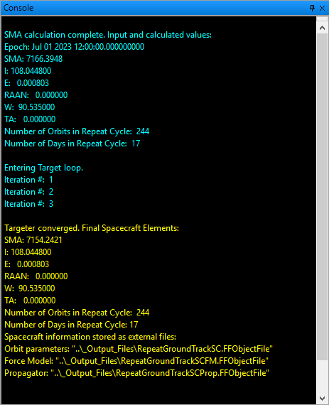
This Mission Plan is designed to be used as a wizard to set up a repeat ground track orbit based off some initial input parameters. An algorithm with a static force model is used to calculate an ideal SMA (semi-major axis) from desired Inclination and Eccentricity values, as well as desired number of orbits and days over which the cycle repeats. The calculated SMA and other orbital elements are then used in a Target loop to refine the SMA values based off a high-fidelity force model that includes solid tides and third-body gravitational perturbations.
One of two algorithms (these can be found on pg. 862 of the 3rd Edition of 'Fundamentals of Astrodynamics and Applications' by David Vallado) can be used to calculate the SMA based off of I and E:
1.Match desired change in longitude over cycle. 2.Match desired number of orbits per day. |
Reset Targeting Loop
This Mission Plan demonstrates the use of the ResetTargetingLoop command in FreeFlyer. The Target command is used to achieve a certain orbit apogee by varying the impulsive delta V, but the seed and perturbation fed into the Targeter are set too high.
If an unrealistically high delta V is attempted, FreeFlyer will reset the Targeting loop with new, lower, seeds.

Console report during Targeting Loop
Runtime Setup Targeting
This Mission Plan demonstrates the use of FreeFlyer's Runtime Setup Targeting mode. The user is able to configure the varies, iterates, and achieves of the targeter in the script without knowing the number of these items when the script is written, allowing the user to load these items in from a file or database at runtime. In this example, FreeFlyer loads targeting events into arrays. Then, in the targeting loop, FreeFlyer loops over the number of events and registers the desired varies and achieves. This example includes four achieves (two inclination, two semi-major axis), and four varies.

Output plots of two inclination achieves and two semi-major axis achieves
Target Apogee - ImpulsiveBurn
This Mission Plan illustrates the use of the Target function to find the value of impulsive delta-velocity required to achieve a given value of semi-major axis.

Orbit trace before and after an Impulsive Maneuver
Target Apogee Height
A 100-lb hydrazine thruster is used in a near-circular orbit to raise apogee to a height of 1000 km.

Output Plot of Spacecraft Apogee and Height
Target Equally Spaced Formation
This Mission Plan demonstrates the advantage of initializing an equally spaced Formation around a circular orbit using J2 Brouwer-Lyddane (BLJ2) elements as opposed to Keplerian elements. The Mission Plan starts by initializing a Formation of Spacecraft using Keplerian elements, propagates for some duration, and outputs the along track drift. After the initial propagation, the Formation is re-initialized using a Procedure that refines the BLJ2A property of each Spacecraft in a Formation so that the distance between neighboring Spacecraft is maintained within a given tolerance over the course of a given propagation time.

Comparision of Brouwer-Lyddane J2 Formation vs. Keplerian Formation
Target Launch Asymptote Right Ascension
This Mission Plan demonstrates how to target the Launch Asymptote Right Ascension (RLA) for an Interplanetary transfer. The Mission Plan starts with a nearly circular parking orbit around Earth. A Transfer orbit insertion burn is performed; varying the Delta-V, Right Ascension of the Ascending Node (RAAN), and the Argument of Perigee (W) to achieve the desired RLA. The RLA is the equatorial east longitude from the vernal equinox. It can be used when designing departure trajectories to match the mission-required outgoing V-infinity vector to the specified launch site location. The DLA is the declination of the outgoing asymptote. In the Targeting loop, FreeFlyer:
•Iterate the Spacecraft (reset the Spacecraft’s properties at the beginning of each iteration) •Vary the Right Ascension of the Ascending Node (RAAN), the Argument of Perigee, and the burn direction •Maneuver the Spacecraft using using the Impulsive Burn object •Achieve a RLA of 57 degrees and a perturbation of 2 degrees •Reports when the solution converges, the delta-V, and achieved RLA |

Spacecraft Targeting a Hyperbolic Interplanetary Trajectory
Target Longitude At Apogee Highly Elliptical
This Mission Plan uses a FreeFlyer Targeting loop to achieve a particular longitude at apogee by varying the duration of a Finite Burn. The Mission Sequence includes the following inside of the Target loop:
•Iterate the Spacecraft (reset the Spacecraft’s properties at the beginning of each iteration) •Vary the duration of a Finite Burn •Maneuver the Spacecraft using the Finite Burn •Propagates Spacecraft to Apogee •Achieves a particular longitude value at this Apogee |

Elliptical Spacecraft Orbit with the specified Longitude at Apogee of 265 degrees
Target Node Rate
This Mission Plan, given values of semi-major axis and eccentricity, uses targeting to solve for the inclination necessary to achieve the node rate required for a sun-synchronous orbit. After solving for the required inclination and reporting the value, the ground trace is drawn on a 2D Map and the orbit is shown in a 3D View of the Earth.
Target SMA
This Mission Plan uses FreeFlyer's Targeting loop to change a Spacecraft's orbit. A Differential Corrector object is used to set the Maximum Iterations to 35. In the Targeting loop, FreeFlyer:
•Iterates the Spacecraft (resets the Spacecraft’s properties at the beginning of each iteration) •Varies the Burn Duration of the Finite Burn object by providing a seed of 30 seconds and a perturbation of 2 seconds •Maneuvers the Spacecraft using the Finite Burn object •Attempts to achieve a semi-major axis of 7500 km +/- 0.1 km •Reports Iteration Number, Iteration Mode, Burn Duration, and semi-major axis to a report on the screen and to an output file •Plots semi-major axis vs. Burn Duration |

Spacecraft orbit before and after a Finite Burn
Thruster Cant Angles
In this example, the Spacecraft has four attached Thruster objects canted out at different angles. This Mission Plan demonstrates how to model a burn that takes Thruster orientation values into account. In order to do that, the AttitudeSystem property of the FiniteBurn object is set to 'Attitude' (3) and the desired attitude to use during the burn in Euler angles is assigned into the FiniteBurn object's BurnDirection property. When the Spacecraft reaches the point in its orbit where we want to perform the burn, it is rotated to the attitude specified in the FiniteBurn and then the individual Thruster orientations are used for directing the delta-v. This Mission Plan also takes advantage of the WhileManeuvering style of loop to perform actions while the burn is taking place.

Spacecraft with Thruster vectors displayed and maneuver portion of orbit in green