These sample Mission Plans show examples of working with FreeFlyer's Optimizer object. After exploring these Mission Plans, continue to the Optimization guide for more information.
Jump to a Mission Plan Description:
Mission Plan |
Engineer |
Mission |
|
• |
|
|
• |
|
|
• |
|
|
• |
|
|
• |
|
|
• |
|
|
• |
|
|
• |
|
|
• |
|
|
• |
|
|
• |
|
|
• |
|
|
• |
|
|
• |
|
|
• |
|
|
• |
|
|
• |
|
|
• |
|
|
• |
|
|
• |
This Mission Plan illustrates the use of FreeFlyer's optimization capability to find a trajectory that can be used to deflect a simulated near-Earth asteroid that is on an impact trajectory with Earth. The asteroid in this simulation (PDC21) is based on the 2021 Planetary Defense Conference Simulation, and is completely fictional. This asteroid does not pose a real threat to Earth.
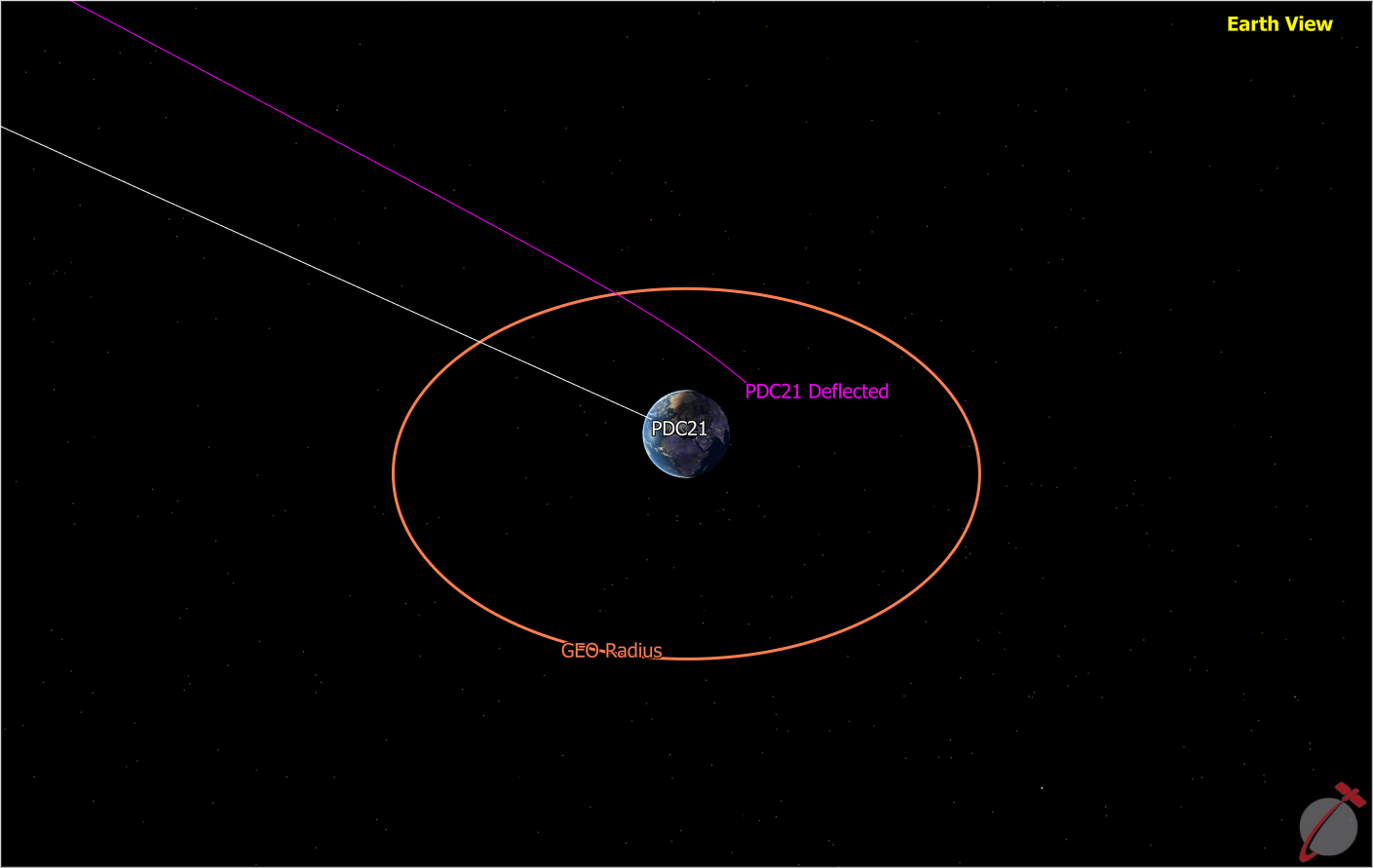
View of the deflected and undeflected asteroids
This Mission Plan demonstrates the use of the Multi-Objective Optimizer to choose which asteroids a spacecraft should visit for an interplanetary mission while minimzing Delta-V and TOF. The candidate asteroids are sorted by their inclination realtive to the origin central body such that solutions are only considered for asteroids within a specified realitve inclination tolerance. Optimization is performed to solve the transfers between the origin and destination with the objectives to conserve the desired number of asteroids to visit, minimize the total Delta-V, minimize the total TOF, and minimize the Delta-V for each transfer.

View of spacecraft departing Earth and visiting a sequence of asteroids
This Mission Plan demonstrates the use of the Multi-Objective Optimizer to schedule as many contacts as possible that occur in darkness between a spacecraft constellation and set of ground stations. First, a constellation of 30 spacecraft and 3 ground stations are configured. The Mission Plan logs the contact opportunity windows over a specified simulation period. Then optimization is performed to maximize the number of contacts scheduled at night, maximize the minimum contact duration and minimize the number of conflicting contacts. When optimization and solution filtering is complete, a file is generated with the contact choice solutions.

Pareto front objective values for contacts to be scheduled at nighttime
Control Acceleration Integration
This Mission Plan demonstrates solving ordinary differential equations (ODEs) using collocation and numerical intergration. The collocation portion is solved using FreeFlyer's TrajectorySegments. First, a Spacecraft is initialized in a slightly elliptical LEO orbit. As the Spacecraft propagates forwards in time 5 hours, TrajectoryNodes are added to the TrajectorySegment. Inside the evaluation loop, the normalized velocity is stored to update and solve the constraints. To compare the integrator solution to the collocation solution, the acceleration and acceleration rate are pulled from the collocation solution and stored in the Spacecraft's ForceModel through the OtherAccelerations Array. While the Spacecraft is propagated using the integrator, the separation between the integrator and collocation solution is plotted for output.
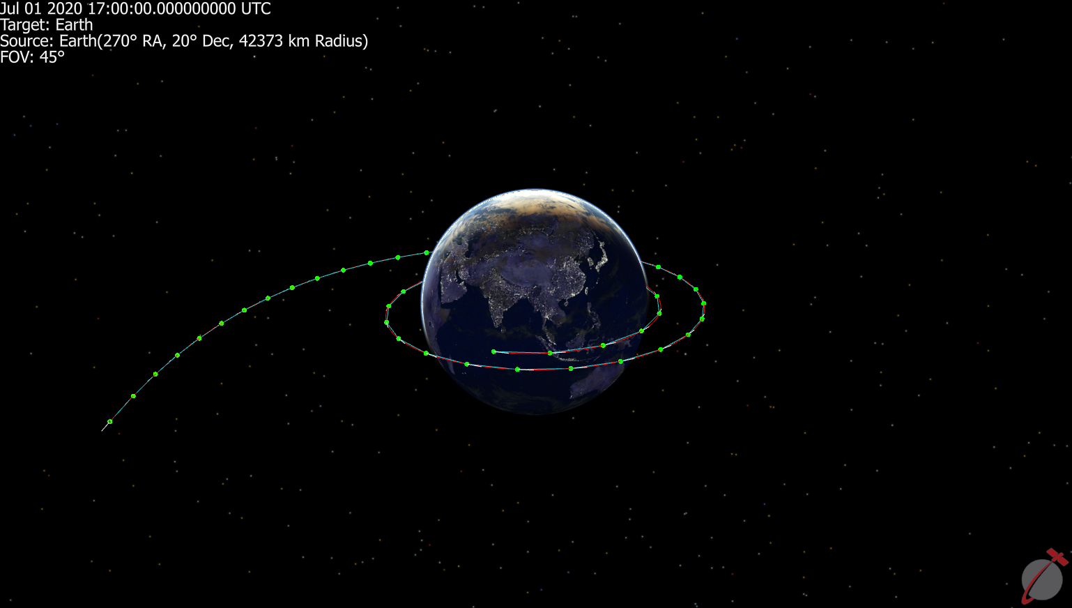
Collocation vs. Integration
Coverage Time Optimization
This Mission Plan illustrates the use of FreeFlyer's optimization capability to configure a constellation of 30 Spacecraft for coverage of a region. The constellation is divided into five planes with six Spacecraft per plane. The optimizer varies the inclination of the planes and the semi-major axis of the Spacecraft. A cost function is established based on the semi-major axis. This enables FreeFlyer to find the best coverage at the lowest altitude. Coverage is optimized over the period of 1/4th of a day. FreeFlyer first runs a propagation loop inside the optimization process to compute the optimal solution. It will then run a final pass of the propagation loop, using the best solution found by the Optimizer, to visualize the results.
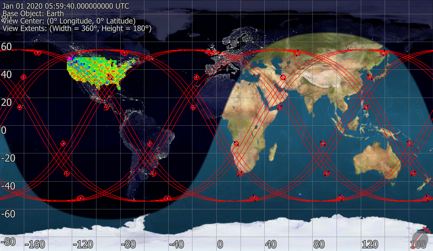
View of optimal constellation configuration
This Mission Plan demonstrates using three TrajectoryPhase objects to optimize the time of flight from Earth to the Earth-Sun L1 point. The Mission Plan starts by calculating an initial guess for a midpoint epoch along the transfer trajectory. The first TrajectoryPhase, preBoost, has five equally spaced TrajectoryNodes over the course of a 3 day propagation. TrajectoryNodes are added to the Earth departure TrajectoryPhase by propagating forwards to the midpoint. TrajectoryNodes are added to the L1 arrival TrajectoryPhase by backwards propagating to the midpoint. The TrajectoryNodes are reconfigured to be in chronological order and the TrajectoryPhase objects are added to the Optimizer. The TrajectoryPhases are added to the Optimizer and inside the evaluation loop, the time between the first node of the Earth departure TrajectoryPhase and the last point in the L1 arrival TrajectoryPhase is minimized.
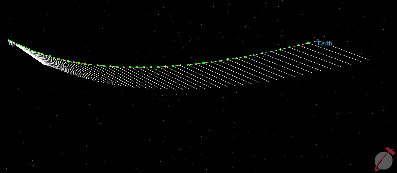
Solar Sail Example
Earth to Mars Continuous Thrust
This Mission Plan demonstrates FreeFlyer's capability to perform a continuous thrust transfer from Earth to Mars using the TrajectoryPhase object. In this demonstration two TrajectoryPhase objects are created, one for the departure from Earth and one for the arrival at Mars. The Mission Plan starts by calculating an initial guess for a midpoint epoch along the transfer trajectory. TrajectoryNodes are added to the Earth departure TrajectoryPhase by propagating forwards to the midpoint. TrajectoryNodes are added to the Mars arrival TrajectoryPhase by backwards propagating to the midpoint. The TrajectoryNodes are reconfigured to be in chronological order and the TrajectoryPhase objects are added to the Optimizer. The Optimizer is configured with general constraints for the Spacecraft's initial and final position and velocity before the evaluation loops. The Optimizer first evaluates the two TrajectorySegments and links the position, velocity, mass, and epoch at the midpoint. Then, the setThrust Procedure is called to configure the thrust for both segments. After the Procedure is called, the Optimzer resets and resolves the problem adding thrust vectors to the ViewWindow. The third evaluation loop minimizes the time of flight for the given configuration and reports the minimized time of flight and required propellant for the trajectory.
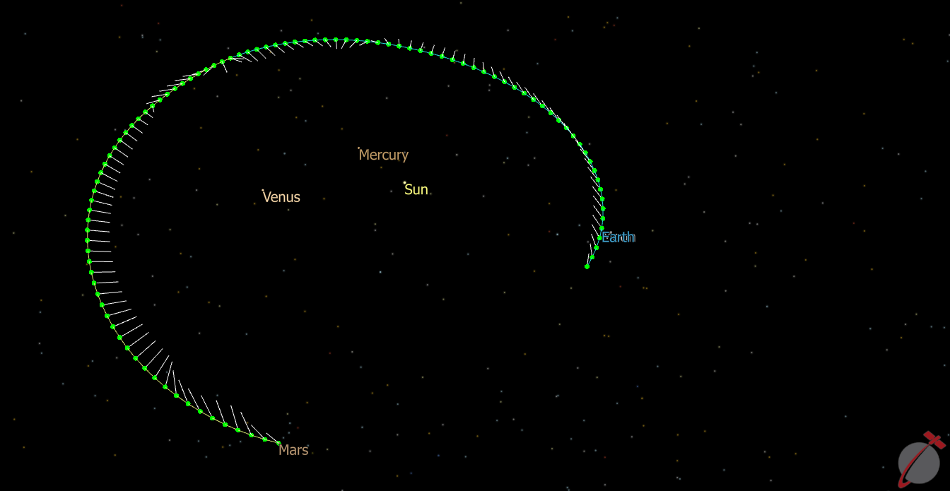
Earth to Mars Continuous Thrust
This Mission Plan demonstrates linking multiple TrajectoryPhase objects to transfer from a geosynchrnous transfer orbit (GTO) to a geostationary orbit (GEO). Three TrajectoryPhase objects are created, one for the parking orbit phase, post boost phase, and transfer phase. After the problem is optimized, the Spacecraft's state is set at the final node in the TrajectoryPhase and propagated for visualization for one period.
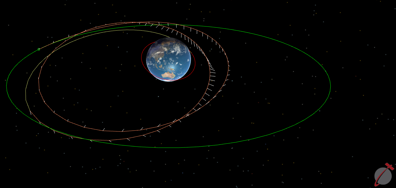
GTO to GEO
This Mission Plan demonstrates configuring a high amplitude halo orbit around the Moon using a TrajectoryPhase. The Spacecraft is initialized using a Rotating Pulsating System. The initial state is given as a non-dimensional CRTBP state vector which is dimensionalized using the Dimensionalize Procedure. The Dimensionalize Procedure converts a non-dimensional CRTBP state vector to dimensional units and shifts the origin of the state vector to the bary-center of the Earth-Moon system. The TrajectoryNodes are added to the TrajectoryPhase object by stepping the Spacecraft to the point in the orbit where the Spacecraft's Y-Position is 0 km relative to the Rotating Pulsating System. The evaluation loop solves the constraints for the optimization problem, then the finalized trajectory is visualized for 2.5 periods.
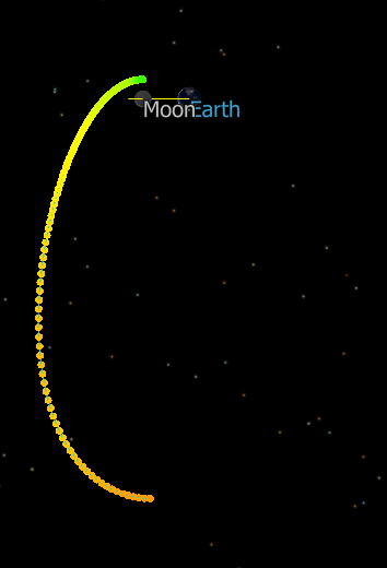
High Amplitude Halo Orbit
This Mission Plan illustrates the use of FreeFlyer's optimization capability to model a transfer between two circular orbits. The Optimizer minimizes the necessary total delta-v across two maneuvers to achieve the desired orbit altitude. A Hohmann transfer uses the least delta-v to transfer a spacecraft between two circular orbits; therefore, a Hohmann transfer is the expected result.
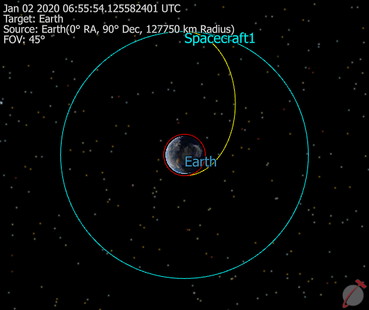
View of final Hohmann transfer trajectory
This Mission Plan demonstrates using the RefineMesh() method to optimize node placements for a Sun-centered orbit. The Mission Plan starts by initializing a Spacecraft in a Sun-centered orbit, and propagating for 1 orbital period adding TrajectoryNodes to the TrajectorySegment. The nodes are re-interpolated using the ResampleNodes() method placing 20 nodes in the first 75% of the trajectory and 101 in the last 25% of the trajectory. The additional nodes in the last 25% of the trajectory are included because the acceleration at those locations is higher so a higher concentration of nodes helps the Optimzer converge on a solution. During the propagation loop, the problem is evaluated until the RefineMesh() method returns 0. The RefineMesh() method inserts TrajectoryNodes in areas where dynamical error is detected and removes TrajectoryNodes where dynamical accuracy is excessive. When the RefineMesh() method returns 0, this means that no dynamical error is detected that violates the CollocationOptions.RelativeErrorTolerance property, thus no nodes are added or removed. This dynamical error is computed by comparing the TrajectoryPhase path to the results of explicit integration using the RK89 propagator.
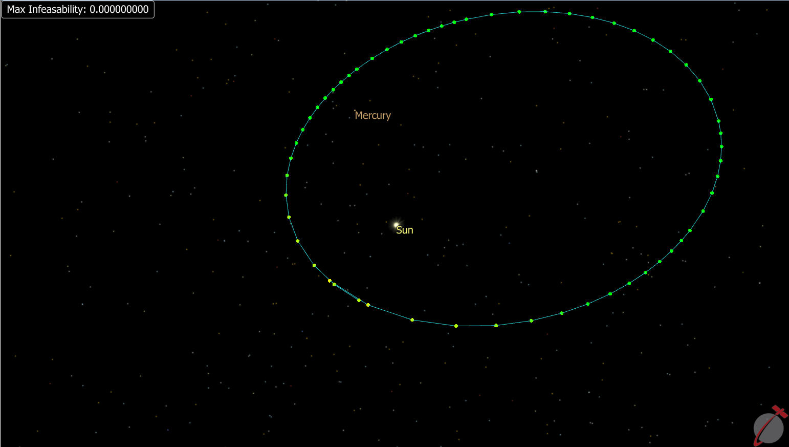
Mesh Refinement
Minimize Analytic Function With Known Derivatives
This Mission Plan demonstrates the use of FreeFlyer's optimization capabilities to minimize an analytic function with known derivatives. The user can choose to solve either the Rastrigin or Rosenbrock function and whether to use numeric or analytic derivatives. Once an optimization configuration is selected, FreeFlyer plots the function using a GraphicsOverlay and solves for the minimum point using the Optimizer.
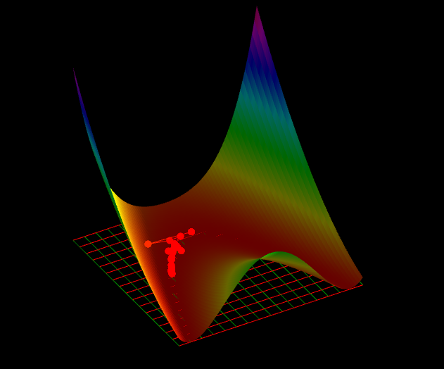
Display of minimum point found in Rosenbrock function
Multiple Impulse Rendezvous
This Mission Plan demonstrates how to transition from collocation to integration when solving a trajectory optimization problem. Collocation often allows for faster convergence than integration but is less accurate. Switching to integration after an initial collocation solve will improve the accuracy of the solution. In this Mission Plan, a chaser spacecraft will execute several maneuvers in order to rendezvous with a target spacecraft. The trajectory to the target is segmented into several trajectory phases with an impulsive maneuver in between each phase. Collocation is used to obtain a rough solution and then the problem is re-solved using integration. The total delta V for the planned maneuvers is calculated. The output shows an angular difference between the maneuvers planned using collocation versus those planned using integration as well as the orbital relative motion.

Difference in planned maneuvers between collocation and integration
This Mission Plan illustrates the use of FreeFlyer's optimization capability to design an optimal Earth to Mars transfer using two impulsive burns. The user can choose the departure and arrival ranges for the analysis as well as whether to minimize delta-V or time of flight. During the optimization process FreeFlyer displays the scaled Jacobian color coded to show the relative correlation of the Constraints and State Variables. This Mission Plan uses the NLopt optimization system.
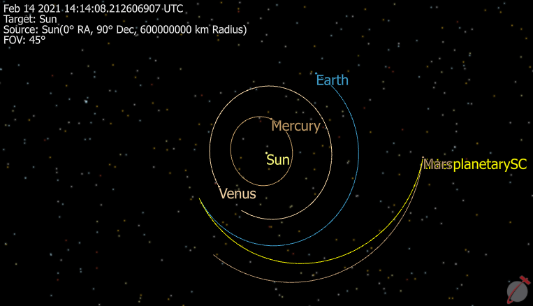
View of Earth to Mars transfer trajectory which minimizes total delta-V
This Mission Plan illustrates the use of FreeFlyer's optimization capability to model an optimal lunar flyby for insertion into a highly elliptical Earth orbit. In order to break the difficult problem down into smaller, more easily solved problems, multiple segments are defined. The Optimizer then patches these segments together while satisfying mission constraints.
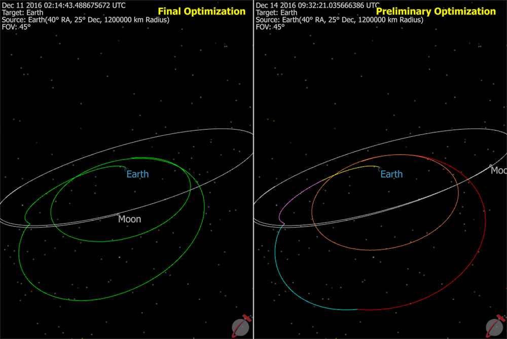
Views of preliminary and final results of optimization processes
This Mission Plan illustrates the use of FreeFlyer's optimization capability to raise a spacecraft's orbit using one finite burn. FreeFlyer finds the optimal burn duration and true anomaly at which to begin the maneuver to minimize the required delta-v.
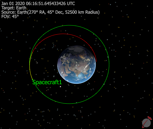
View of final orbit raising trajectory which minimizes delta-v
Optimizer Seeded From Targeter
This Mission Plan uses FreeFlyer's optimization capability to minimize the total required delta-V of a finite maneuver to adjust a Spacecraft's elliptical orbit to achieve a longitude of 265 degrees at apogee. A Targeting loop is run before the optimization process to generate initial guesses for the burn parameters, which are then passed in to the Optimizer as initial values.
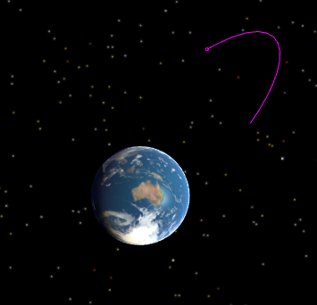
View of final trajectory achieving desired longitude at apogee
This Mission Plan demonstrates satellite orbit decay impact predictions and maneuver planning for targeted re-entry. An initial Monte Carlo simulation is performed to visualize the predicted re-entry impact footprint. Then, an optimal re-entry maneuver is calculated in order to minimize the distance between the initial impact footprint and the South Pacific Oceanic Uninhabited Area (SPOUA), which is considered to be the official 'satellite graveyard'.
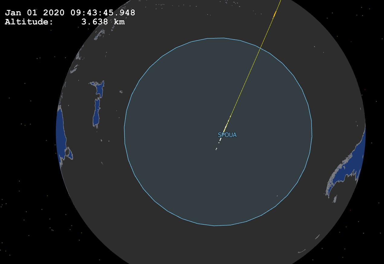
Optimal re-entry impact footprint
This Mission Plan demonstrates the use of the Multi-Objective Optimizer to solve Schaffer's 2nd problem - a single variable problem with two objectives to be minimized. The Pareto front hypervolume initially increases as the optimizer finds acceptable solutions, then the hypervolume plateaus as the optimizer stops finding better solutions. Pareto front culling is used to keep the number of stored solutions low and lower the computational time needed to solve the problem. When the Pareto front is culled, multiple similar solutions are replaced by one representative solution. This is visually depicted by the changing data point density on the 'Pareto Front Objective Values' plot.

Pareto front objective values showing changing data point density due to culling the pareto front
This Mission Plan demonstrates the use of the Multi-Objective Optimizer to solve the traveling salesman problem - an optimization problem where the goal is to minimize the total distance traveled for a salesman to visit a group of cities, such that the salesman visits each city once before returning to the starting city.

Route minimizing the total distance traveled for a salesman to visit 16 cities