FreeFlyer’s Mission View provides powerful tools for generating realistic visualizations. One technique for making the visualizations more realistic is to set custom 3D models for the Vehicle (Spacecraft or GroundVehicle) in your analysis. There are two approaches to working with custom 3D models in FreeFlyer, each discussed below. For simple visualization purposes, you can specify the model via the properties of the Spacecraft and GroundVehicle objects, or, for more customization, you can create a ThreeDModel object to associate with a Spacecraft or Ground Vehicle. Users can also test whether a vector intersects a Spacecraft or GroundVehicle object's 3D model by following the details in the Vectors and Coordinate Systems guide.
You can also choose not to display a 3D model for your Spacecraft or GroundVehicle, and instead display only its name and/or an icon (an image file). This can be useful when you don't have an accurate 3D model, or when you want to distinguish between different orbiting or terrestrial objects at a glance even when zoomed out. Icons are also useful when you don't have access to information about the attitude (orientation) of an orbiting object, and you don't want to misrepresent the attitude of the object by displaying a 3D model.
The following Sample Mission Plans (included with your FreeFlyer installation) demonstrate the use of the customized 3D models:
|
Supported File Types
FreeFlyer can ingest a number of different 3D model formats. The following is a comprehensive list of the 3D model file types supported by FreeFlyer:
•Discreet 3DS (.3ds, .prj) •LightWave / Modo Object (.lwo, .lxo) •Wavefront Object (.obj) •Stereolithography (.stl) |
When working with 3D models, please be aware of the following:
•3D models in all formats are unitless. This means that when a model is created using 3D model software, the creator can associate the length "1" with any unit of their choice (mile / kilometer / inch / etc.) and thus scale it however they like. FreeFlyer, however, must associate a unit to the imported 3D model draw it in a ViewWindow, and so FreeFlyer assumes units of meters. This means that a 1x1x1 cube 3D model will be drawn as a 1-meter edge cube in FreeFlyer. You can apply a scaling factor to the model's size using the Spacecraft.BodyScale or GroundVehicle.BodyScale property.
•The ThreeDModel.Scale property can be used to scale the size of implicit dimensions associated with the 3D model, such as those returned when using the ThreeDModel.GetGroupBoundingBox method. The Scale property assumes that the 3D model's dimensions are in units of meters, similar to the Spacecraft.BodyScale or GroundVehicle.BodyScale property.
•The coordinates in a 3D model are referenced from a global right-handed coordinate system, which FreeFlyer aligns with the BCS of the Spacecraft or Ground Vehicle. Any attitude offsets defined for the vehicle will also apply to the 3D model. If a Spacecraft 3D model has a boom of a solar array pointing out the y-axis, then in FreeFlyer that boom will point in the y-direction of the Spacecraft BCS.
•The coordinates in a 3D model are referenced from a global origin, which FreeFlyer positions coincident with the origin of the vehicle BCS. If the 3D model is offset from the origin, then it will appear offset in the Mission View in FreeFlyer. If this is not desired, the ThreeDModel.SetGroupTranslation method can be used to translate the model. •Some models render differently in different viewers, or require a very specific configuration to ensure that things like textures are shown correctly. If your model is not displaying correctly in FreeFlyer, consider consulting the person who provided you the model to see if they can provide any insight. An internet web search for documentation on the file format that you're using will also provide useful information. |
There are numerous tools available that allow the user to inspect and manipulate 3D model files. Some of these tools are designed to handle a specific format, and others are designed to handle 3D models of multiple formats. Each of these tools may provide a guide or tutorial of its own for working with 3D models, and many of these guides also include instruction on how to import the various 3D models accepted in FreeFlyer. Below is a partial list of some free tools that are available for download online.
•Blender (www.blender.org) •Anim8or (www.anim8or.com) •gCAD3D (www.gcad3d.org) |
Using 3D Models with a Vehicle
There are two primary supported means for how to configure a Vehicle's 3D model, and the key difference is in how much control is necessary over the 3D model itself. In simple cases where full control is not necessary and the group functionality (described below) is not used, simply adjusting the Vehicle's 3D model directly makes the most sense. Conversely, if you are using groups and want to visualize rotating parts on your 3D model, or need to associate multiple 3D models to a single Vehicle, it makes sense to use the ThreeDModel object and associate it to the Spacecraft or GroundVehicle.
Adjusting the Vehicle's 3D model directly
When working with a 3D model through the Spacecraft or GroundVehicle object, you have access to the following options in FreeFlyer script:
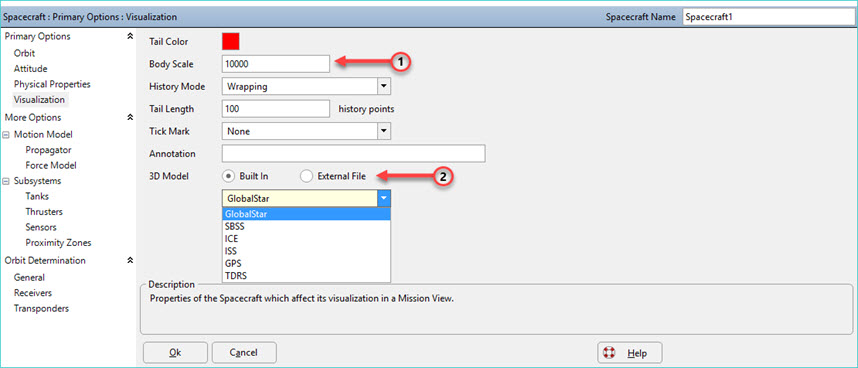
1.Set the size of the 3D model using the Spacecraft.BodyScale or GroundVehicle.BodyScale property, which applies a scale factor to increase or decrease the size of the vehicle model in a Mission View. The units of a model are assumed to be in meters.
2.Set the 3D model by setting the Spacecraft.ThreeDModelFile or GroundVehicle.ThreeDModelFile property. You can choose one of the built-in models using the syntax "Internal::ModelName" (e.g., "Internal::GlobalStar").
|
These options can also be configured through the Visualization page of the Spacecraft or GroundVehicle object editor.
Note: Changing a vehicle's BodyScale property will also scale the translation values used for translating the 3D model's groups. This means that if you have a very small BodyScale value, your translation values will have to be very large for appreciable translation distances. When scaling is applied the 3D model body axes are being scaled relative to the longest edge of the bounding box; while the bounding box is drawn in the vehicle body frame.

Visualization page of the Spacecraft object editor
Adding a ThreeDModel Object to a Vehicle
For more complete control of the analysis and visualization of your 3D Model, the ThreeDModel object should be used. This object is not available via the Object Browser, so it must be created in FreeFlyer script. Once the object has been created, assign it a file name just as you would assign the Vehicle's ThreeDModel property in the example above.
ThreeDModel ThreeDModel1; ThreeDModel1.ModelFilename = "myModelFile.3ds"; |
Once the object has been created, you can associate it with a vehicle using the Spacecraft.SetThreeDModel or GroundVehicle.SetThreeDModel method:
Spacecraft1.SetThreeDModel(ThreeDModel1);
// or
GroundVehicle1.SetThreeDModel(ThreeDModel1); |
Note: You can change the 3D model associated with a vehicle by using the Spacecraft.SetThreeDModel or GroundVehicle.SetThreeDModel method (or by setting the string value of Spacecraft.ThreeDModelFilename or GroundVehicle.ThreeDModelFilename) more than once over the course of your Mission Plan. Any ViewWindow objects displaying the vehicle will dynamically update.
Group Control
In order to articulate portions of the ThreeDModel, you must define Groups. Each group can represent a piece of the model to which you would like to apply a unique orientation and/or translation, such as a solar array or an antenna. The first step is to create the group(s) and specify which objects within the 3D model file will belong to the group(s).
Note: Entire 3D models can be placed as separate groups within a single ThreeDModel object. In this way, the user can associate as many separate 3D models as necessary to a Vehicle and then adjust and synchronize them as necessary using the group handling logic below.
// You can create a group for a piece of the 3D model. ThreeDModel1.AddGroup("SolarArray"); ThreeDModel1.AddGroup("CameraPiece");
// You can store the contents of the 3D Model in a String Array ThreeDModel1.ReportGroupTree(StringArray1);
// You can move objects to a group one at a time, or in an Array using the StringArray input ThreeDModel1.MoveGroup("SolarArray",StringArray1[0]); ThreeDModel1.MoveGroup("SolarArray",StringArray1[1:10]);
// You can also create sub-groups and add them to a previously created group ThreeDModel1.AddGroup("SolarArray","Camera"); ThreeDModel1.MoveGroup("SolarArray/Camera","CameraPiece");
// Finally, you can remove groups and all 3D data associated with them ThreeDModel1.RemoveGroup("SolarArray/Camera"); |
Once the groups have been defined, there are several "Set" methods that allow you to apply an offset to a group relative to the rest of the ThreeDModel.
// Set the position of the pivot point about which rotations are applied. // This point is defined in absolute model coordinates. // You can use 3 Variables, an Array, or a Vector to input the pivot position. ThreeDModel1.SetGroupPivotPosition("SolarArray",10,0,0);
// Set the orientation offset for all components in the 3D model file that are contained within the specified group. // You can use 4 Variables or an Array of quaternions to set the orientation. ThreeDModel1.SetGroupOrientation("SolarArray",ArrayOrientation);
// Set the translational offset for all elements in the 3D model file that are contained within the specified group. // You can use 3 Variables or an Array to input the translation. ThreeDModel1.SetGroupTranslation("SolarArray/Camera",ArrayTranslation);
// Set the total position and orientation offset for all components in the // 3D model file that are contained within the specified group. // You can use a CoordinateSystem object to input the transformation. ThreeDModel1.SetGroupTransformation("SolarArray/Camera",CoordinateSystemTransformation); |
You can now extract useful information from the ThreeDModel using various "Get" and "Report" methods.
// Get the absolute position of the group pivot point after all transformations are applied, referenced to the Vehicle's BCS. ArrayGetPosition = ThreeDModel1.GetTransformedGroupPosition("SolarArray");
// Get the absolute orientation, as a quaternion, of the group after all transformations are applied, referenced to the Vehicle's BCS. ArrayGetOrientation = ThreeDModel1.GetTransformedGroupOrientation("SolarArray");
// Calculates the bounding-box of the vertices for a defined group. Returns the volume of the box. ThreeDModel1.GetGroupBoundingBox("SolarArray/Camera",ProximityZone1); ThreeDModel1.GetGroupBoundingBox("SolarArray",ArrayBoxPosition, ArrayBoxSize);
// Get the volume of the entire ThreeDModel bounding box, using a ProximityZone or a set of Array objects, in km^3. ThreeDModel1.GetModelBoundingBox(ProximityZone1); ThreeDModel1.GetModelBoundingBox(ArrayBoxPosition, ArrayBoxSize);
// Reports the group's direct parent as a String. myString = ThreeDModel1.ReportGroupParent("SolarArray");
// Reports the group's immediate children as a StringArray. myStringArray = ThreeDModel1.ReportGroupChildren("SolarArray");
// Reports the group's entire descendant list as a StringArray. myStringArray = ThreeDModel1.ReportGroupDescendants("SolarArray"); |

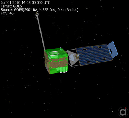
Sample ThreeDModel with a Bounding Box ProximityZone shown in green around the spacecraft main body. Rotations have been applied to the Solar Array and Camera.
See Also
•ThreeDModel Properties and Methods
•Proximity Zones Guide
•Spacecraft Visualization Guide
•GroundVehicle Visualization Guide
•ViewWindow - Rotating an External 3ds Model Sample Mission Plan