The ProximityZone object can be attached to a Spacecraft for use in proximity analysis and visualization. For example, you may wish to know at what attitudes a Sensor's view is blocked by a Spacecraft hardware component. A ProximityZone can be established around that component of the Spacecraft, and you can determine when a Vector representing the Sensor's field of view (FOV) intersects with the ProximityZone.
ProximityZones can also be used to perform conjunction assessment, by calculating the intersection times with other Spacecraft or ProximityZones. ProximityZones can also be used to visualize a Spacecraft's covariance.
The following Sample Mission Plans (included with your FreeFlyer installation) demonstrate the use of the ProximityZone object:
|
Properties
ProximityZone Shape
The ProximityZone can be one of three shapes:
•Spherical •Ellipsoid •Rectangular |
You can set the radius for a spherical ProximityZone, or the X, Y, Z dimensions of an ellipse or rectangle:
// Add a ProximityZone to SpacecraftSpacecraft1.AddProximityZone("proximityZone1"); // Set ShapeSpacecraft1.ProximityZones[0].MaximumRangeShape = 2; //Ellipsoid// Set SizeSpacecraft1.ProximityZones[0].Size = {500, 400, 300}; |
ProximityZone Position
The X, Y, Z location of the center of the ProximityZone with respect to the Spacecraft's body coordinate system (BCS) can be specified through the Object Editor or FreeFlyer script. By default, the center of the ProximityZone will be co-located with the center of the Spacecraft BCS.
// Set PositionSpacecraft1.ProximityZones[0].Position = {0, 0, -0.5}; |
ProximityZone Orientation
A sequence of Euler Angles can be specified to orient the ProximityZone with respect to one of the following reference frames:
•International Celestial Reference Frame (ICRF) •Velocity Normal Binormal (VNB) •Local Vertical Local Horizontal (LVLH) •Body Coordinate System (BCS) •UVW •RIC |
// Set OrientationSpacecraft1.ProximityZones[0].MaxRangeAttitudeFrame = 2; // LVLHSpacecraft1.ProximityZones[0].Orientation = {30, 0, 15}; |
Visualization
You may specify the color of ProximityZone, and whether it is rendered translucent or as a wire frame. Additionally, you can use the TickScale property to specify the distance between tick marks on the axes attached to the ProximityZone.
// Visualization SetupSpacecraft1.ProximityZones[0].Color = ColorTools.Yellow; Spacecraft1.ProximityZones[0].ShellType = 1; // Wire Frame Spacecraft1.ProximityZones[0].TickScale = 75; |

Proximity Zone Object Editor with Preview Window
Example: Vector Intersection
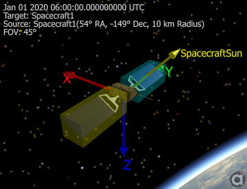
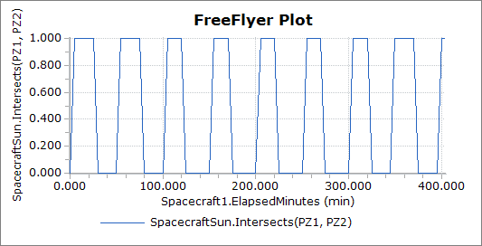
In this example, two ProximityZones are added to a Spacecraft. The ProximityZones represent a bounding boxes around the Spacecraft's solar panels. A Vector that points from the center of the Spacecraft to the Sun is also created, and the intersection of the Vector with the two ProximityZones is calculated. The resulting output plot and view are shown below. For a summary of the coverage and contact output methods in FreeFlyer organized by observer and target object type, see the Contact Method Summary.
Spacecraft Spacecraft1; Vector SpacecraftSun;
Spacecraft1.AddProximityZone("pz1"); Spacecraft1.AddProximityZone("pz2");
Alias PZ1 = Spacecraft1.ProximityZones[0]; Alias PZ2 = Spacecraft1.ProximityZones[1];
// Edit PZ1 PZ1.MaximumRangeShape = 3; // Box PZ1.ShellType = 0; // Translucent PZ1.Color = ColorTools.Cyan; PZ1.Size = {0.5, 1.3, 0.5}; PZ1.Position = {0, 1.75, 0}; PZ1.MaxRangeAttitudeFrame = 3; // BCS
// Edit PZ2 PZ2.MaximumRangeShape = 3; // Box PZ2.ShellType = 0; // Translucent PZ2.Color = ColorTools.Yellow; PZ2.Size = {0.5, 1.3, 0.5}; PZ2.Position = {0, -1.75, 0}; PZ2.MaxRangeAttitudeFrame = 3; // BCS
// Edit SpacecraftSun Vector SpacecraftSun.BuildVector(9, Spacecraft1, Sun); SpacecraftSun.DrawMethod = 1; SpacecraftSun.MagnitudeScaleFactor = 0.5;
// Set Spacecraft Orientation Spacecraft1.EulerAngles = {90, 0, 45};
While (Spacecraft1.ElapsedTime < TIMESPAN(1 days));
Plot Spacecraft1.ElapsedTime.ToHours(), SpacecraftSun.Intersects(PZ1, PZ2); Step Spacecraft1; Update ViewWindow1;
End; |
Note: As of FreeFlyer 7.3, the default timing precision mode is nanosecond precision mode. For older Mission Plans that have not yet been converted from millisecond precision mode, the syntax for working with times is different. See the timing precision mode page for more information.
See Also
•ProximityZone Properties and Methods
•Vectors and Coordinate Systems Guide
•Vehicle 3D Models Article