The Vector and CoordinateSystem objects provide powerful and convenient methods for Vector analysis and manipulation. Vectors can be displayed in 2D and 3D visualizations and can be used to easily determine the range and direction to a specified target, calculate intersections with Proximity Zones or Vehicle 3D Models, or define custom coordinate systems. CoordinateSystems can be used to define the orientation of ThreeDModels, ProximityZones, Sensors, and Spacecraft objects. Both Vectors and CoordinateSystems can be updated dynamically using FreeFlyer script, and can be very useful in contact analysis. For a summary of the coverage and contact output methods in FreeFlyer organized by observer and target object type, see the Contact Method Summary.
The following Sample Mission Plans (included with your FreeFlyer installation) demonstrate the use of the Vector and Coordinate System objects:
|
Note: FreeFlyer also includes an Array object, which contains a one-dimensional set of numbers. Arrays can be used to store and manipulate data. Arrays can have any number of elements, while Vectors always have three elements. You can convert between Vectors and Arrays using syntax such as: Array1 = Vector1.Element or Vector1.Element = Array1.
Vectors
Vector objects can be defined thirteen different ways, listed in the table below. The vector type indicates how the Vector object is constructed. For example, to create a vector that points from one FreeFlyer object to another (Type 9):
Vector SpacecraftToEarth; SpacecraftToEarth.BuildVector(9, Spacecraft1, Earth); |
This vector will now point from Spacecraft1 toward the Earth. For information on the input arguments to build each vector type, see the "BuildVector" method on the Vector Properties and Methods page.
Value |
Vector Type |
0 |
CARTESIAN |
1 |
SPHERICAL |
2 |
CROSS_PRODUCT |
3 |
NORMALIZED_VECTOR |
4 |
BODY_AXIS |
5 |
BODY_ANGULAR_MOMENTUM |
6 |
BODY_POSITION |
7 |
BODY_VELOCITY |
8 |
EXISTING_X_AXIS |
9 |
OBJECT_TO_OBJECT |
10 |
ANTI_VECTOR |
11 |
STAR |
12 |
OBJECT_TO_STAR |
Note: All Vector objects are reference frame agnostic; it is up to the user to keep track of which reference frame the vector is defined with respect to. For the types of BODY_AXIS, BODY_ANGULAR_MOMENTUM, BODY_POSITION, BODY_VELOCITY, OBJECT_TO_OBJECT, and OBJECT_TO_STAR, the Cartesian elements of the Vector object are defined with respect to ICRF.
Vector Visualization
The Vector object includes several properties for adjusting visualization. For example, to display a vector as an arrow instead of a line, and to change the color from the default yellow to blue, use:
SpacecraftToEarth.DrawMethod = 1; SpacecraftToEarth.Color = ColorTools.Blue; |
Vector Intersection with 3D Models or Proximity Zones
The Vector object can be tested to see if it is intersecting a Spacecraft 3D model or a Proximity Zone. For more information on working with 3D models, see the Vehicle 3D Models section in the Viewing Objects guide. Information on working with Proximity Zones is available in the Proximity Zones section of the Coverage and Contact Analysis guide.
The Intersects method simply returns a 1 if the vector is intersecting a 3D model or a proximity zone or a 0 if it is not. This is an instantaneous method and relies heavily on the step size used during propagation.
Report SpacecraftToEarth.Intersects(PZ1); // Instantaneous intersection evaluation for a Proximity Zone
-- OR --
Report SpacecraftToEarth.Intersects(TDM1); // Instantaneous intersection evaluation for a 3D Model |
For higher fidelity calculations on intersection times, you can use the IntersectionTimes interval method. This method has the ability to return the exact times when the vector begins and ends intersection with the object of interest. See the Interval Methods page for more information.
Report SpacecraftToEarth.IntersectionTimes(PZ1) to "VectorIntersections.txt";
-- OR --
Report SpacecraftToEarth.IntersectionTimes(TDM1) to "VectorIntersections.txt"; |
Output:
Intersection Event Start Epoch End Epoch Duration (Min) |
SpacecraftToEarth --> TDM1 Aug 28 2020 08:32:39.656 Aug 28 2020 08:32:53.641 0.233083330 |
CoordinateSystems
CoordinateSystem objects can be built in several ways:
CoordinateSystem1.BuildCoordinateSystem(1, Vector1, 2, Vector2); |
![]() Using a direction cosine matrix
Using a direction cosine matrix
CoordinateSystem1.SetAttitudeMatrix(DCM_Matrix); Matrix1 = CoordinateSystem1.GetAttitudeMatrix(); |
CoordinateSystem1.SetEulerAngles(alpha, beta, gamma, "3-1-2"); Array1 = CoordinateSystem1.GetEulerAngles("3-1-2"); |
CoordinateSystem1.SetQuaternion(q1, q2, q3, q4); Array1 = CoordinateSystem1.GetQuaternion(); |
![]() Using a chain of existing coordinate systems
Using a chain of existing coordinate systems
CoordinateSystem1.BuildCoordinateSystem(CoordinateSystem2, CoordinateSystem3, CoordinateSystem4); |
![]() Using the Body Coordinate System of Spacecraft, CelestialObject, or Sensor objects
Using the Body Coordinate System of Spacecraft, CelestialObject, or Sensor objects
CoordinateSystem1.BuildCoordinateSystem(Spacecraft1); CoordinateSystem2.BuildCoordinateSystem(Spacecraft1_Sensor1); CoordinateSystem3.BuildCoordinateSystem(CelestialObject1); |
Note: CoordinateSystem objects are agnostic to reference frame. You may create a CoordinateSystem object and define its axes with respect to a reference frame, but FreeFlyer does not keep track of this reference frame. It is up to the user to manage the reference frame definitions. The default CoordinateSystem object, before being edited by changing any properties or calling the BuildCoordinateSystem method, represents the ICRF frame.
Example 1: Setting a Spacecraft's Attitude
CoordinateSystems can be used to set a spacecraft’s attitude so that its tail is always pointed to the sun. To do this, first use the BuildVector and BuildCoordinateSystem methods as follows:
Vector SpacecraftSun; Vector SpacecraftEarth; Vector SunSpacecraft;
CoordinateSystem TailtoSun;
SpacecraftSun.BuildVector(9,Spacecraft1,Sun); SpacecraftEarth.BuildVector(9,Spacecraft1,Earth); SunSpacecraft.BuildVector(10,SpacecraftSun);
TailtoSun.BuildCoordinateSystem(1,SunSpacecraft,2,SpacecraftEarth);
SpacecraftSun.DrawMethod = 1; SpacecraftSun.MagnitudeScaleFactor = 0.5;
SpacecraftSun.DrawMethod = 1; SpacecraftSun.Color = ColorTools.Yellow;
TailtoSun.Epoch = Spacecraft1.Epoch; |
Then, there are two approaches to applying this "TailtoSun" CoordinateSystem to a Spacecraft object:
1. Use the Spacecraft.SetOrientation(CoordinateSystem) method to update the Spacecraft's attitude when desired (for example, this can be done within a While loop to set the orientation once per Step). With this option, the Spacecraft's AttitudeRefFrame property must first be set to "ICRF".
Spacecraft1.AttitudeRefFrame = "ICRF";
Spacecraft1.SetOrientation(TailtoSun);
View Spacecraft1, SpacecraftSun; |
2. Use the Spacecraft.SetAttitudeRefFrame(CoordinateSystem) method to reference the Spacecraft's attitude to the specified CoordinateSystem object (properties such as Spacecraft.Attitude, Spacecraft.Quaternion, and Spacecraft.AttitudeMatrix will be reported with respect to the specified CoordinateSystem). Then, use the Spacecraft's attitude properties to set the orientation to indicate zero rotation with respect to its new attitude reference frame, so that the Spacecraft's attitude is perfectly aligned with the CoordinateSystem.
Spacecraft1.SetAttitudeRefFrame(TailtoSun);
Spacecraft1.Quaternion = {0, 0, 0, 1};
View Spacecraft1, SpacecraftSun; |
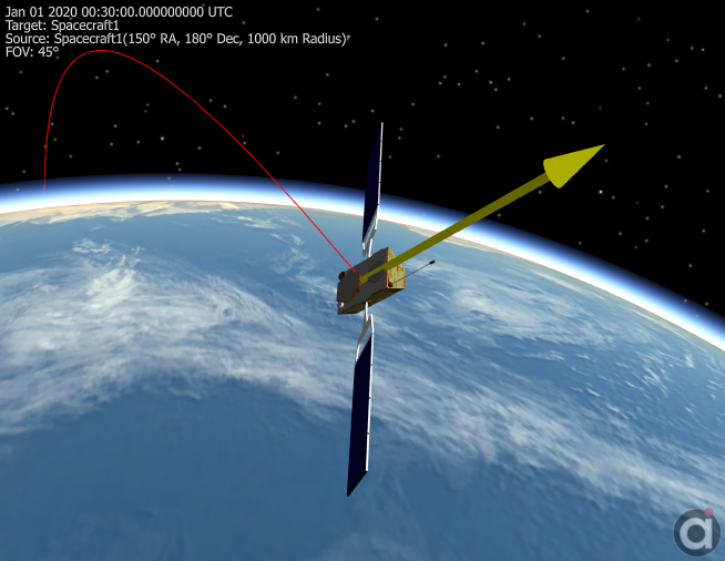
With either approach, the result is a Spacecraft that points tail-to-sun, as shown in the image below. The difference is that with approach #1, the orientation is applied only at the time(s) specified using the Spacecraft.SetOrientation() method in the Mission Sequence, whereas with approach #2, the CoordinateSystem is automatically re-evaluated every time the Spacecraft is propagated or maneuvered, and the Spacecraft's attitude is maintained with respect to the CoordinateSystem during each integration step. See the Attitude Reference Frames page for more information.
To apply another rotation after setting the initial orientation, Coordinate Systems can be "chained" together. The following code will set the Spacecraft x-axis to the sun, and apply a 30 degree "roll" around this new x-axis:
Vector SCtoSun; Vector SCtoEarth; CoordinateSystem sunPointing; CoordinateSystem rotateBody; CoordinateSystem finalAttitude;
// New coordinate system to be aligned with the Sun SCtoSun.BuildVector(9, Spacecraft1, Sun); SCtoSun.DrawMethod = 1; SCtoSun.MagnitudeScaleFactor = 0.8;
SCtoEarth.BuildVector(9, Spacecraft1, Earth);
sunPointing.BuildCoordinateSystem(1, SCtoSun, 3, SCtoEarth);
// Coordinate system with additional rotation rotateBody.SetEulerAngles(30,0,0,"1-2-3");
// Coordinate systems "chained" together to create final orientation finalAttitude.BuildCoordinateSystem(rotateBody, sunPointing);
// Apply orientation Spacecraft1.SetAttitudeRefFrame(finalAttitude); Spacecraft1.Quaternion = {0, 0, 0, 1}; |
Example 2: Defining a Custom Coordinate System through 2 Vectors
The following lines of script will set up 2 vectors that can be used to define a Spacecraft LVLH coordinate system. Vector SC_Position is type 9, "Object-to-Object." The SC_Velocity vector is type 7, "Body Velocity." Then, the Coordinate System is built using these two vectors.
Variable stat; Vector SC_Position; Vector SC_Velocity; CoordinateSystem LVLH_Frame;
stat = SC_Position.BuildVector(9, Spacecraft1, Earth); stat = SC_Velocity.BuildVector(7, Spacecraft1);
// First axis (X) points in the velocity direction, third axis (Z) points along the Spacecraft1 anti-radius stat = LVLH_Frame.BuildCoordinateSystem(1, SC_Velocity, 3, SC_Position); |
Since this coordinate system rotates in time, it needs to be updated any time the state of "Spacecraft1" is updated. To update the CoordinateSystem object, add a line inside the propagation loop of the script to synchronize the coordinate system in time with the spacecraft, like so:
LVLH_Frame.Epoch = Spacecraft1.Epoch; |
The functionality provided by the CoordinateSystem object facilitates vector rotations. To rotate a Spacecraft-Sun Vector into the Spacecraft LVLH frame, do the following:
Vector Spacecraft2Sun; |
Note: the vector is converted in place, so after the ConvertToCoordinateSystem call, the Spacecraft2Sun Vector is referenced from the LVLH frame. All Vector and CoordinateSystem events return a status, captured here by a Variable called "stat", indicating whether or not the operation completed successfully.
Example 3: Defining a Mars-Fixed Coordinate System
Build a Mars-fixed Coordinate System using two Vectors of type 4 - "Body Axis."
Vector mars_x; |
As always, update the CoordinateSystem at every step of propagation by synchronizing its Epoch with the Spacecraft object.
mars_fixed.Epoch = Spacecraft1.Epoch; |
Example 4: Defining a Custom Coordinate System through Euler Angles
Euler-type rotations can be performed in just a few lines using FreeFlyer’s CoordinateSystem and Vector objects. After creating the objects, define the Coordinate System using the “SetEulerAngles” method, and define the Vector as the z-axis of the custom reference frame:
CustomCS.SetEulerAngles(alpha,beta,gamma,"3-1-2"); Vector1.Element = {0, 0, 1}; |
This defines the custom Coordinate System by rotating the Geocentric (ICRF) system by alpha degrees about the 3rd axis, beta degrees about the 1st axis, and gamma degrees about the 2nd axis.
Next, rotate the Vector from the custom frame to the ICRF frame:
Vector1.ConvertFromCoordinateSystem(CustomCS); |
Example 5: Rotating and Displaying a Vector Drawn from a Spacecraft
A Vector can be used to show where a Spacecraft body axis (in this case the x-axis) will end up after a rotation is applied, for example. A custom Coordinate System can be used to apply the rotations to the Vector itself via direction cosine matrix (DCM), and some conversion allows the Vector to be displayed properly fixed with respect to the Spacecraft body coordinate system (BCS) in a ViewWindow.
After first creating the Vector and Coordinate System objects, align the Vector to the x-axis and set the Euler angles to rotate the Coordinate System (the Array and Matrix are used as containers for conversion purposes):
Vector vecRotXAxis; Array arrVector[3]; Matrix matDCM[3, 3]; CoordinateSystem csRotation;
// Build vector along x axis in ICRF vecRotXAxis.BuildVector(4, Spacecraft1 ,1); arrVector = vecRotXAxis.Element;
// Create Coordinate system with arbitrary rotation for DCM csRotation.SetEulerAngles(90, 45, 0, "2-3-2"); matDCM = csRotation.GetAttitudeMatrix();
Report matDCM; |
Next, apply the rotations and conversions. The vector will appear fixed relative to the Spacecraft BCS:
// Transpose DCM to get from BCS' to BCS matDCM = matDCM.Transpose();
// Convert vector into BCS arrVector = AttitudeConvert(0, 3, Spacecraft1, arrVector);
// Apply rotation in BCS arrVector = (matDCM*arrVector.ToColumnMatrix()).ToArrayRowMajor();
// Convert vector back into ICRF for visualization arrVector = AttitudeConvert(3, 0, Spacecraft1, arrVector); |
Lastly, instruct FreeFlyer where to draw the Vector from.
// Make sure vector is drawn from Spacecraft, not Earth vecRotXAxis.VisualOffset = Spacecraft1.Position;
vecRotXAxis.Element = arrVector;
vecRotXAxis.DrawMethod = 1; vecRotXAxis.MagnitudeScaleFactor = 0.05;
View Spacecraft1, vecRotXAxis; |
Example 6: Vector Intersection Evaluation
Vectors can be used to do intersection calculations with 3D models. The Vector.Intersects() instantaneous method will return a 1 if the vector is intersecting the specified 3D model. The Vector.IntersectionTimes() interval method will return the exact time when the vector intersects the 3D model and the time when the vector no longer intersects the 3D model.
The following example shows how the interval method IntersectionTimes is used to determine when a vector intersects the solar arrays on the ISS.
TimeSpanArray AccessTimes; Array AccessEvents;
While (ISS.ElapsedTime < TIMESPAN(2 hours));
numInt = Vector1.IntersectionTimes(ISS.ThreeDModelObject, AccessTimes, AccessEvents);
For i = 0 to numInt - 1; Switch (AccessEvents[i]); Case 1: Report "Intersection with Solar Array begins at " to Console; Report AccessTimes[i].ConvertToCalendarDate() to Console; Break; Case 2: Report "Intersection with Solar Array ends at " to Console; Report AccessTimes[i].ConvertToCalendarDate() to Console; Break; End; End; End; |
The image below shows where the vector first intersects the solar arrays.

Image showing a vector intersecting the solar array.
See Also
|
•Vector Properties and Methods •CoordinateSystem Properties and Methods |