These sample Mission Plans cover topics relating to propagating a spacecraft when the central body is not Earth. After exploring these Mission Plans, continue to the Interplanetary Analysis Guide for more information.
Jump to a Mission Plan Description:
Mission Plan |
Engineer |
Mission |
• |
• |
|
• |
• |
|
• |
• |
|
• |
• |
|
• |
• |
|
• |
• |
|
• |
• |
|
• |
• |
|
• |
• |
|
• |
• |
|
• |
• |
|
• |
• |
|
• |
• |
|
• |
• |
|
• |
• |
|
• |
• |
|
• |
• |
|
• |
• |
|
• |
• |
Asteroid Contact
This Mission Plan shows how to create Celestial Objects and determine contact between Celestial Objects and a Spacecraft.

View of planet orbits and contact between the asteroids and the spacecraft
Asteroid TCA
This Mission Plan takes in and processes known TCA data for an asteroid named Toutatis and the Earth from NASA Jet Propulsion Laboratory (JPL). Once processed, the Mission Plan visualizes both the orbit of the asteroid from an Ecliptic view and the way that the asteroid would appear to a Groundstation on Earth, in this case Goldstone, during its transit at TCA.
The TCA epoch for this particular celestial encounter is Dec 29, 2016 14:15:00.000 Barycentric Dynamical Time (TDB).

View of Earth and Toutatis at TCA
B-Plane Targeting
This Mission Plan demonstrates the use of FreeFlyer's built-in B-Plane functions for interplanetary trajectory targeting. The B-Plane is a plane that contains the central body and the incoming asymptote of a hyperbolic approach trajectory.
The B-Vector lies along the intersection of the B-Plane (yellow) and the trajectory plane (blue). The magnitude of the B-Vector (BMag) is the distance from the center of the celestial body to the point where the trajectory crosses the B-Plane. The vectors T and R are used as axes of the B-Plane. The angle Theta is the angle between the B-Vector and the T-Vector. The velocity and normal components of an Impulsive Burn are Targeted to achieve the user-specified values for BMag and Theta.

Visualization of Mars B-Plane and Trajectory Plane
Cardinal Points Using Moon
This Mission Plan demonstrates the use of the CardinalPoints interval method in FreeFlyer to calculate the times at which a Spacecraft will be at a Cardinal Point relative to the Moon. The times are reported to a DataTableWindow, along with the corresponding alpha angle (the angle between the Spacecraft and the Sun). In the ViewWindow, each cardinal point is marked using a GraphicsOverlay object. In addition, the alpha angle is plotted as a function of time.

ViewWindow showing the cardinal point labels.
Celestial Object
FreeFlyer allows the user to create custom objects (ie., a planet, moon, asteroid, or comet) via the Celestial Object. The user can specify a CelestialObject’s movement using SPICE Files. Any CelestialObject can be included as a force in any Spacecraft's Force Model. For information on obtaining SPICE files, see the SPICE Files page of the Ephemerides section of the Appendix.
This Mission Plan demonstrates the creation of a custom Celestial Object; in this case, Io. The ephemeris for Io was downloaded from the website ftp://naif.jpl.nasa.gov/pub/naif/ and the texture is supplied in the image io.jpg. Several properties and methods of the Celestial Object are also demonstrated.

Spacecraft orbiting the custom Celestial Object Io
To learn more about topics related to this Mission Plan, see the Celestial Objects page of the Interplanetary Analysis Guide.
Circular Restricted Three Body Problem
The Circular Restricted Three Body Problem (CRTBP) is an idealized system that simplifies (relatively) the interaction of a spacecraft with nearby bodies, making it extremely useful early on in the space mission design process. This Mission Plan is a simplification and is accomplished by assuming that one of the three bodies (the spacecraft) is of negligible mass and that the other two bodies are spherical and in circular orbits about their shared center of mass. One last element of the CRTBP is the rotating frame of reference that is used. In order to facilitate the underlying math of the CRTBP, a coordinate system is implemented that rotates in sync with the motion of the primary masses. When the system is viewed in this rotating frame, the two primary bodies appear motionless.

Lyapunov family about L1 in the Earth-Moon Rotating Frame.
Custom Lunar Coordinate System
This Mission Plan demonstrates how to convert a spherical moon-fixed orbital state into a Cartesian, inertial reference frame. This example uses a combination of FreeFlyer's built-in conversion functions and custom matrix math.

Custom Lunar Coordinate System with orbiting Spacecraft
Distant Retrograde Orbit
This Mission Plan demonstrates a Distant Retrograde Orbit (DRO) in FreeFlyer. The Orbiter will be propagated for 28 days, completing two complete orbits around the Moon. During the Orbiter's propagation, the Rotating Libration Points (RLP) for the Earth-Moon system will be similarly displayed. As the Orbiter is propagated, a plot of the gravitational accelerations from the Earth and the Moon it experiences is populated. This plot demonstrates the effects seen at the Libration points, particularly L1 and L2.

Body Fixed View of Distant Retrograde Orbit
Earth Mars Hohmann Transfer
This Mission Plan models a low-fidelity interplanetary Hohmann Transfer trajectory from Earth to Mars. In this example, the orbits of both Earth and Mars are modeled as perfectly circular and coplanar, and all parameters are calculated using analytical methods.
Hohmann Transfer Trajectory from Earth to Mars
Earth Moon Shadow Times
This Mission Plan demonstrates how to calculate Earth and Moon shadow times and generate a custom-formatted report shown on the Console window and written out to a file.

ShadowTimes Report for Earth and Moon
High Value Asteroids
This Mission Plan reads in a list of high value asteroids as determined by NASA and then visualizes them with object icons based on their type, makeup, and importance. The size of every asteroid indicates its value relative to the other asteroids, thus making the largest asteroids the most valuable. A GridWindow is embedded within the Ecliptic view to provide a color coding and symbolic legend for the asteroids based on their compositions.
After initialization, the entire list of asteroids is then propagated over time to show their orbits relative to one another and the nearby planets with tail lengths scaled by their respective orbital periods.

View showing High Value asteroids by type and approximate value
Hyperbola Arrival Maneuver
This Mission Plan demonstrates how to apply different maneuver options in order to adjust a hyperbolic arrival trajectory at Venus. Each color represents a different possible burn magnitude. All burns are aligned to the co-velocity direction. The first three burn options result in closed (elliptical) orbits. The fourth option results in a departure hyperbola.

Four possible arrival maneuvers for a hyperbolic Venus-approach trajectory
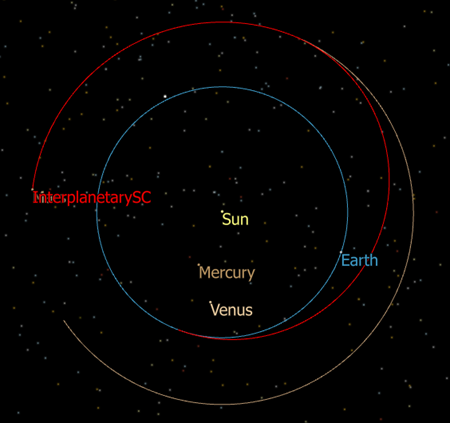
Lambert Transfer Calculation
This Mission Plan demonstrates how to use FreeForm scripting to calculate a Lambert transfer trajectory. The user specifies the departure date, time of flight, departure planet, arrival planet, and whether to use a prograde or a retrograde orbit. FreeForm script is used to solve for the universal anomaly X using Newton’s algorithm. The equations and methodology used to solve Lamberts problem are adapted from the book "Orbital Mechanics for Engineering Students" by H. D. Curtis. The View Window shows a solar system view displaying all planets and the interplanetary spacecraft trajectory. Only the Sun's point mass gravitational effects are modeled.

Lambert Transfer from Earth to Mars in 200 days
Libration Point Orbiter
This Mission Plan demonstrates the use of Rotating Libration Point (RLP) coordinates in FreeFlyer. An orbiting spacecraft is configured with initial coordinates with respect to the RLP frame. 2D Plots and 3D Views display the X-Y, X-Z, and Y-Z planes of the co-rotating RLP frame. At the start of each Y=0 plane crossing, the FreeFlyer Target command is used to determine the required Y-velocity in order to maintain the halo orbit with zero X-velocity at the next Y=0 plane crossing. Lines in green and yellow indicate the Earth-L1 and Sun-L1 vectors, respectively.

Halo orbit around the Sun-Earth-Moon L1 point
Lunar GroundStation
This Mission Plan shows how to place a GroundStation on the surface of any Celestial Object. In this case, we are placing a GroundStation called LEM on the Moon. The GroundStation can be used for contact and communication analysis. We are using the PassData interval method to determine line of sight between the Spacecraft and the GroundStation.
This concept can be applied to any other Celestial Object, including custom, user-defined Celestial Objects.

Lander shown on the surface of the Moon with orbiting Spacecraft
Mars Flybys
This Mission Plan examines the differences between a front-side and back-side hyperbolic flyby of Mars. The front-side flyby passes between Mars and the Sun, and pushes the Spacecraft into a new orbit with a larger semi-major axis. The back-side flyby passes behind Mars with respect to the Sun, and pulls the Spacecraft into a new orbit with a smaller semi-major axis.

Two possible trajectories after a Mars flyby
Rings of Jupiter
This Mission Plan demonstrates a Spacecraft orbiting Jupiter and the various data that can be derived from that orbit. The spacecraft performs multiple Hohmann transfers, determines when it crosses through the various rings of Jupiter, and determines when it has access to Jupiter's moons Callisto, Europa, Ganymede, and Io.

The spacecraft in contact with all the moons about Jupiter
Solar Eclipse
This Mission Plan demonstrates how to use the PercentEarthShadow and PercentMoonShadow methods and plots the results using the PlotScatterSeries object.

Plot of the percent of shadow of the Earth and Moon that the spacecraft is within.
Star Catalog
This Mission Plan shows how to populate a StarField with data from a FreeFlyer-formatted star catalog. Other supported formats are OpenUniverse and SkyMap catalogs. Once the catalog is initialized, outputs show the stars' names, ID's, and magnitudes; a polar plot shows the positions of the stars.