A blockage diagram is a 2D representation of blockage due to a combination of 3D CAD model configuration and custom angular regions when viewed from a given viewpoint. In FreeFlyer, the BlockageDiagram object loads in a bitmap based .xpm file to represent the blockage diagram. Using the BlockageDiagram object, contact evaluations can be done between a Spacecraft and: another Spacecraft, a Groundstation, a CelestialObject, a position, a Star, or a Vector. In addition to the BlockageDiagram object, the LookAngleFrame object can be used to define a look angle frame. This frame helps define the angles LookAngle1 and LookAngle2 with respect to a boresight vector.
These diagrams are used for several purposes:
•Visualizing blockage scenarios •Evaluating blockage over a given time span •Visualizing blockage over a given time span |
The following Sample Mission Plans (included with your FreeFlyer installation) demonstrate the use of the BlockageDiagram object:
|
Properties
Filename
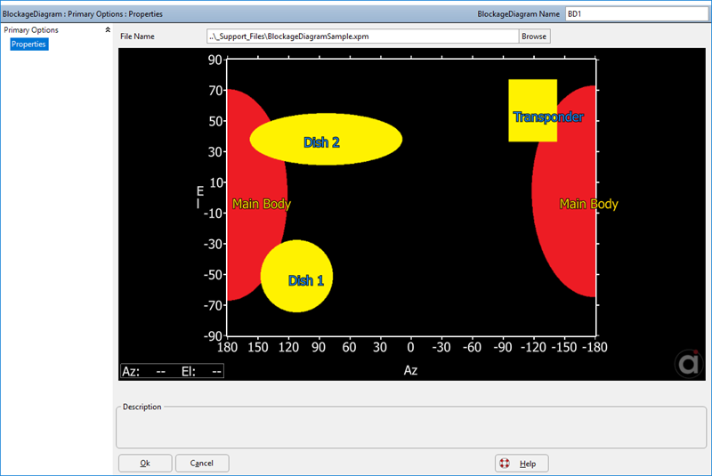
The BlockageDiagram object must be associated with a modified bitmap (.xpm) file. The .xpm file holds the visualization of the blockage and the look angle information. Once you load the proper blockage diagram, you should be able to see the diagram in the BlockageDiagram object GUI, as pictured below. If no diagram loads up, the bitmap file is not properly formatted and FreeFlyer will throw a runtime error if you try to run the Mission Plan.

BlockageDiagram GUI with a loaded blockage diagram.
You can also set the file path in FreeForm:
BlockageDiagram BD1;
BD1.Filename = "..\_Support_Files\BlockageDiagramSample.xpm"; |
Height and Width
The Height and Width properties hold the height and the width of the blockage diagram in pixels. The blockage diagram dimensions must adhere to the following:
•Height = LookAngle2Range*3 + 1 •Width = LookAngle1Range*2 + 1 |
Where LookAngle2Range cannot be larger than 360 for an independent LookAngleFrame or 180 for a dependent LookAngleFrame, and LookAngle1Range cannot be larger than 360. The extra pixels in the height and width reflect that pixels are centered around the specified look angles, e.g. if the minimum is -180, the first pixel represents -180.25 to -179.75. With these limitations, the maximum size for blockage diagrams with independent and dependent LookAngleFrames is 1081x721 (Height x Width) and 541x721 respectively.
Report BD1.Height; // Displays the height of the blockage diagram Report BD1.Width; // Displays the width of the blockage diagram |
Methods
The BlockageDiagram object will contain look angle frame information (i.e. pointing information) taken from the blockage diagram that was loaded. This information points the center of the blockage diagram in a direction relative to the spacecraft's Body Coordinate System. The look angle frame information can be pulled out of the BlockageDiagram and placed into the LookAngleFrame object.
Position and Pointing
The GetOffsetPosition method returns the Cartesian components of the offset vector from the origin of the spacecraft BCS. You can set the offset position by using the SetOffsetPosition method.
PosArrayOut = BD1.GetOffsetPosition(); // Returns the offset position as an array {x,y,z} BD1.SetOffsetPosition(PosArrayIn); // Modify the offset position as an array {x,y,z} |
The pointing information can be exported to the LookAngleFrame object, which allows more control over the look angle frame. The LookAngleFrame object is described in more detail below.
LookAngleFrame LAF1;
BD1.GetLookAngleFrameConfiguration(LAF1); |
Overlay Text
Text can be displayed on the blockage diagram to be used as annotations. The GetOverlayText method can retrieve overlay text that was brought in from the blockage diagram, if any. The following FreeForm will retrieve the overlay text information from the BlockageDiagram object.
StringArray contents; Array xPositions; Array yPositions; Array positionModes; Array Reds; Array Greens; Array Blues;
BD1.GetOverlayText(contents, xPositions, yPositions, positionModes, Reds, Greens, Blues);
Report contents[0]; // Returns the text to be displayed. Report xPositions[0], yPositions[0]; // Returns the x and y position of the text (units in pixels or in degrees) Report positionModes[0]; // Returns the mode with which the position was interpreted. Report Reds[0]; // Returns the red component of the RGB value. Report Greens[0]; // Returns the green component of the RGB value. Report Blues[0]; // Returns the blue component of the RGB value.
|
Conversely, the AddOverlayText method can add text to the blockage diagram. You are able to position the overlay text anywhere on the blockage diagram by specifying the position mode and the position where the text will be placed.
BD1.AddOverlayText(contents, xPositions, yPositions, positionModes, Reds, Greens, Blues); |
The position mode is specified with these values:
Value |
Label |
0 |
Look Angles : xPosition and yPosition are treated as look angle 1 and 2 values respectively. |
1 |
Pixels Upper Left : xPosition and yPosition are treated as pixel locations with the origin in the upper left. |
2 |
Pixels Lower Left : xPosition and yPosition are treated as pixel locations with the origin in the lower left. |
Blockage Test
There are various methods available to test whether or not a source object can see the target object based on the blockage diagram. The source's body-fixed frame defines the base for the blockage diagram look angle frame orientation. The method LineOfSight is an instantaneous evaluation that determines if the source can see the target using the blockage diagram. The target argument can be a position, a Vector, a CelestialObject, a Groundstation, another Spacecraft, or a Star.
If (BD1.LineOfSight(SourceSC,TargetSC)); Report "Source has line of sight of the target" to Console; End; |
For a high fidelity evaluation of line of sight, the LineOfSightTimes interval method will return the exact times at which the source loses sight of the target spacecraft. An example of the LineOfSightTimes interval method is provided below.
Look Angle Frames
The LookAngleFrame object provides more flexibility in setting up a look angle frame to be used across multiple blockage diagrams. The object holds the look angle frame and allows for various calculations to be made. The look angle can be transferred to and from the BlockageDiagram object through the GetLookAngleFrameConfiguration and the SetLookAngleFrameConfiguration methods.
Properties
The BoresightAxis property of the LookAngleFrame object lets you choose an axis of the look angle frame as the boresight axis. By default this value is set to the +X axis.
LookAngleFrame LAF1;
BD1.GetLookAngleFrameConfiguration(LAF1);
LAF1.BoresightAxis = 2; // Sets the boresight axis to the +Y direction |
The MountOrientation provides access to the orientation of the look angle frame with respect to the spacecraft BCS. The NullOrientation property sets a roll-pitch-roll sequence to be applied with respect to the MountOrientation, describing the look angle frame coordinate system.
Matrix DCMatrix;
DCMatrix = [1, 0, 0; 0, 1, 0; 0, 0, 1];
LAF1.MountOrientation = DCMatrix; LAF1.NullOrientation = {90, 0, 45}; |
The LookAngle1Type and LookAngle2Type properties allow the user to set the type of rotation represented by the first and second look angle, respectively. The rotations are with respect to the coordinate system defined by the MountOrientation and the NullOrientation properties.
LAF1.LookAngle1Type = 3; // The type of rotation for LookAngle1. Set to +yaw LAF1.LookAngle2Type = 4; // The type of rotation for LookAngle2. Set to -roll |
Note: Invalid combinations of LookAngle1Type, LookAngle2Type, and BoresightAxis will result in run time errors.
Methods
The CalculateLookAngles method calculates the look angles for the target object with respect to the look angle frame. The GetBoresightVector method returns a vector based on the mounting matrix, the null orientation, and the boresight axis.
Variable lookAngle1; Variable lookAngle2;
Array FinalArray;
LAF1.CalculateLookAngles(SourceSC, targetSC, lookAngle1, lookAngle2);
Report lookAngle1, lookAngle2;
FinalArray = LAF1.GetBoresightVector(); |
Output:
lookAngle1 |
lookAngle2 |
34.8 |
78.5 |
Example 1: LineOfSightTimes
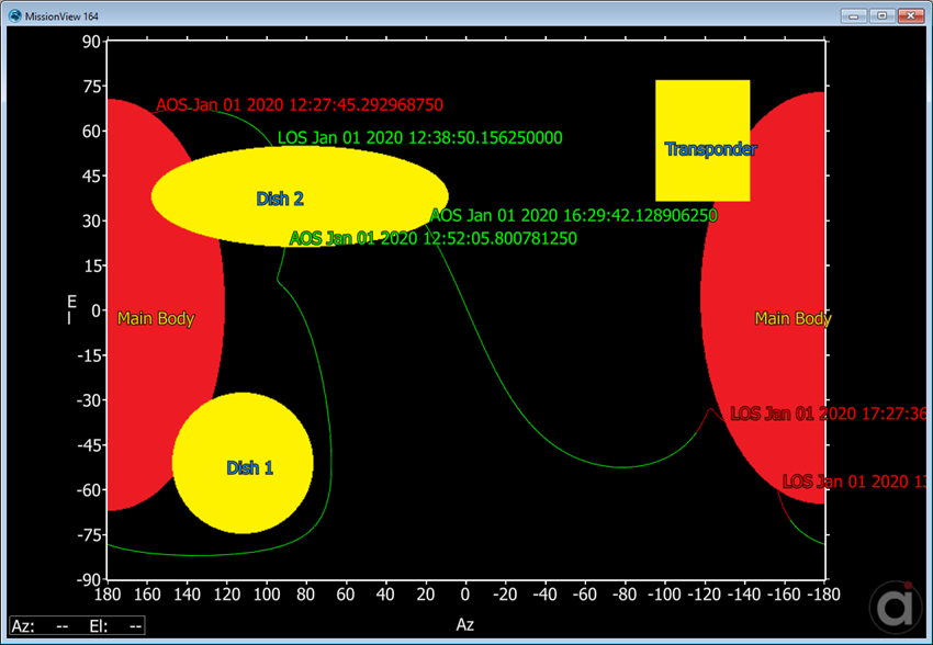
In this example, the LineOfSightTimes interval method is used to evaluate when a target spacecraft is entering and going out of sight of the source spacecraft. For a summary of the coverage and contact output methods in FreeFlyer organized by observer and target object type, see the Contact Method Summary.
Spacecraft Sat1; Spacecraft target;
BlockageDiagram BD1;
BD1.Filename = "..\_Support_Files\BlockageDiagramSample.xpm";
Array eventTypes; TimeSpanArray eventTimes; Variable i;
Variable numLOSEvents; Variable hasLineOfSight;
While (Sat1.ElapsedTime < TIMESPAN(0.25 days));
numLOSEvents = BD1.LineOfSightTimes(Sat1, target, eventTimes, eventTypes);
// Changes tail color to red if Sat1 is being occulted by the Earth If (Sat1.Contact(target)) then; target.Color = ColorTools.Lime; Else; target.Color = ColorTools.Red; End;
// Blockage diagram line of sight calculations If (numLOSEvents != 0);
Save Sat1; Save target;
For i = 0 to numLOSEvents-1;
Step Sat1 to (Sat1.Epoch == eventTimes[i]); Step target to (target.Epoch == eventTimes[i]);
If (eventTypes[i] == 1); target.Annotation = "AOS " + target.EpochText; hasLineOfSight = 1; Else; target.Annotation = "LOS " + target.EpochText; hasLineOfSight = 0; End;
ViewWindow1.SetTailState(target.ObjectId, hasLineOfSight);
ViewWindow1.Update(); target.Annotation = "";
End;
Restore Sat1; Restore target;
End;
ViewWindow1.Update(); Step Sat1; Step target;
End; |
Note: As of FreeFlyer 7.3, the default timing precision mode is nanosecond precision mode. For older Mission Plans that have not yet been converted from millisecond precision mode, the syntax for working with times is different. See the timing precision mode page for more information.

Output showing Spacecraft AOS and LOS.
See Also
•BlockageDiagram Properties and Methods
•LookAngleFrame Properties and Methods