These sample Mission Plans cover various aspects of Spacecraft Propagation in FreeFlyer. After exploring these Mission Plans, continue to the Spacecraft Propagation guide for more information.
Jump to a Mission Plan Description:
Mission Plan |
Engineer |
Mission |
• |
• |
|
• |
• |
|
• |
• |
|
• |
• |
|
• |
• |
|
• |
• |
|
• |
• |
|
• |
• |
|
• |
• |
|
• |
• |
|
• |
• |
|
• |
• |
|
• |
• |
|
• |
• |
|
• |
• |
|
• |
• |
|
• |
• |
|
• |
• |
|
• |
• |
|
• |
• |
|
• |
• |
|
• |
• |
|
• |
• |
|
• |
• |
|
• |
• |
|
• |
• |
|
• |
• |
AHF Generation
This Mission Plan demonstrates the ability to generate Attitude History files in the FreeFlyer format. To learn more about topics related to this sample Mission Plan, see the Ephemerides and Attitude History Files reference.
A-Train Orbit Plane With Debris
This Mission Plan shows the debris from the 2009 Cosmos2251/Iridium33 collision with respect to the 'A-Train' orbit plane. The A-Train consists of Aqua, CloudSat, CALIPSO, PARASOL, and Aura. When elements of the debris field intersect the orbit plane, they momentarily turn white. An 'X' marks the spot where an element of the debris field has crossed the orbit plane within the apogee and perigee height of the A-Train. Miss distances of < 1000 km are reported to the Console.

A-Train orbital plane with Iridium/Cosmos debris
To learn more about topics related to this sample Mission Plan, see the Lists and Formations guides and the Proximity Zones section of the Coverage and Contact Guide.
Attitude Reference Frames
This Mission Plan illustrates the different available Spacecraft Attitude Reference Frames. The built-in attitude reference frames are: Geodetic, LVLH, ICRF, UVW, and VNB. FreeFlyer also provides the ability to reference the Spacecraft's attitude to a custom CoordinateSystem object. The view shows 6 Spacecraft, each with a '0, 0, 0' attitude with respect to one of these frames. For the Spacecraft referenced to a custom CoordinateSystem, a Sun-pointing CoordinateSystem is used. The viewpoint is fixed to the LVLH Spacecraft.

Six Spacecraft in the same orbit, referenced to each of the available attitude reference frames
CCSDS Ephemeris With Covariance
This Mission Plan demonstrates how to propagate a Spacecraft along the vectors in a CCSDS OEM ephemeris file and visualize the covariance data in the file as a 3D error ellipsoid using a ProximityZone. The Watch Window displays information from the header of the CCSDS file.
Convert Attitude Time Quaternions AHF
This Mission Plan demonstrates how to convert an STK attitude history file containing 'AttitudeTimeQuaternions' to a FreeFlyer-formatted AHF file containing time and attitude quaternions. This sample assumes that the STK epoch in the header is in the format below, which will be split into 5 StringArray elements ('ScenarioEpoch', Day, Month, Year, Time), reassembled into FreeFlyer's epoch format, and then converted to MJD using EpochScan.
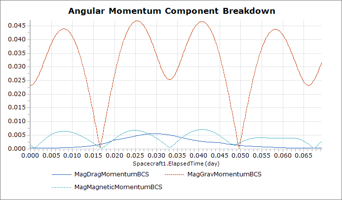
Drag/Grav/Magnetic Momentum
This Mission Plan calculates drag, magnetic, and gravitational forces, torques, and momentums on an orbiting spacecraft.
Ephemeris Generation
This Mission Plan demonstrates the ability to generate ephemerides in the FreeFlyer, CCSDS OEM, and STK formats. To learn more about topics related to this sample Mission Plan, see the Ephemerides and Attitude History Files reference.
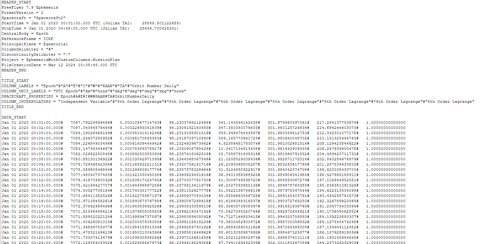
Ephemeris with Custom Columns
This Mission Plan illustrates how to create an ephemeris file with custom columns and a custom delimiter (#). The Ephemeris file is created by propagating Spacecraft1 and using the Put Command. The file is imported to propagate Spacecraft2 using the LoadEphemeris Method. The file is also imported to propagate Spacecraft2 backwards in time using the PropagationDirection Method. The Ephemeris file is written to the _Output_Files directory and saved as 'SCephem_wCustomColumns.FFephem'.
Ephemeris with Custom Reference Frame
This Mission Plan highlights the capability of FreeFlyer's Ephemeris v3 format to use a custom reference frame for the ephemeris data. In this example, a custom Earth Fixed (at epoch) frame is defined at the epoch: Jan 15 2020 12:30:00.000.
The PositionVelocityConvert() function is used at every time step of a 6 hour propagation loop to convert the Spacecraft's state vector from ICRF to the Earth Fixed at epoch frame. These states are then added into the ephemeris as custom columns of data that are not mapped to any spacecraft properties. The ephemeris is then read back into the Mission Plan and imported into a new Spacecraft object using a smaller step size. FreeFlyer interpolates the data in the custom reference frame due to the smaller step size before converting the data back to ICRF and assigning it to the new Spacecraft object.
Note: An 8th order Lagrange interpolator is used for this particular analysis with the resulting plotted data appearing more smooth due to the increased number of propagation steps taken.

Plot showing interpolated data vs input data
Ephemeris with Discontinuity
This Mission Plan illustrates how to create an Ephemeris file with a discontinuity. The Spacecraft is propagated for two hours, maneuvered using a ImpulsiveBurn and propagated for two hours. The Ephemeris object is written out in the FreeFlyer ephemeris format to the "_Output_Files" directory and saved as 'SCephem_wDiscontinuity.FFephem'. The discontinuity is marked with a discontinuity delimiter "|" and a vector comment "Burn 1". See the Creating an Ephemeris File guide for more information.

Ephemeris File displaying a Discontinuity
Flat Plate Box with Four Wings
This Mission Plan demonstrates how to use a PlateModel to model a simple Spacecraft with a bus and 4 solar panels. The bus is created using the PlateModel.AddBoxOfPlates() method. The solar panels are created individually using the Plate.ConfigureRectangularShape() method and are set up to use two-axis perfect sun tracking articulation. During the 1 day propagation, the SRP force on the PlateModel is plotted and the Spacecraft is shown in a 3D ViewWindow. Note how the SRP Force goes to zero when the Spacecraft is in shadow.

Flat Plat Box with Four Wings
Flat Plate Lunar Capsule
This Mission Plan demonstrates how to model a capsule using Plates. The top and bottom of the capsule are configured using the Plates.ConfigureCircularShape() method. The side panels are created using a Procedure which solves for the vertex points connecting the top and bottom of the capsule. The normals of the side panels are drawn and colored depending on which faces can see the Sun. During the half day propagation, the SRP Force and SRP Torque are plotted.

Flat Plate Capsule
Flat Plate SRP Area Scale Factor
The SRP Area Scale Factor scales the force generated due to SRP on the Plate and can be specified by the user to simulate 'self-shadowing' where one Plate generates less force because it is behind another Plate.
This Mission Plan sets up two boxes of plates, one in front of the other. The SRPAreaScaleFactor for the +X side of the main 'bus' is set to 0.5 because the Plate is partially blocked by the 'module'. Similarly, the SRPAreaScaleFacotr for the -X side of the 'module' is set to 0 becuase the Plate is 100% obscured by the main 'bus'. In the ViewWindow the 'module', colored cyan, can be seen partially blocking the main 'bus', colored gold, and the PlotWindow shows the resulting magnitude of SRP Force for the PlateModel.

Simulate Self-Shadowing Example
HCW Coordinate Sets Propagation
This Mission Plan demonstrates the ability to propagate the different coordinate sets available to the HCW propagator. Each Coordinate Set Spacecraft starts from the same initial orbit and is propagated using the HCW relative motion propagator. During the propagation, the position difference between each Coordinate Set and the relative motion reference Spacecraft is plotted.

Plot of the Coordinate Set Propagation Position Difference
Highly Elliptical Variable Step Prop
This sample Mission Plan propagates a spacecraft in a Highly Elliptical Orbit (HEO) using the Runge-Kutta 8(9) propagator in Variable Step Size mode.
Notice that as the spacecraft approaches Perigee the velocity of the spacecraft increases, and therefore FreeFlyer must decrease the integration step size in order to satisfy the user-defined error tolerance. However, as the spacecraft approaches Apogee, the velocity of spacecraft decreases, and therefore FreeFlyer does not require the integration step size to be as small in order to satisfy the user-defined error tolerance. Therefore, the integration step size increases.

Highly elliptical orbit with propagation steps marked by + Signs
Integrator Comparison
This Mission Plan shows the variation when propagating spacecraft using the propagators built into FreeFlyer.

A view of the different integrators propagating through a low-Earth orbit
Lifetime
This Mission Plan demonstrates use of FreeFlyer to determine spacecraft lifetime in a low-altitude orbit. The Bulirsch Stoer VOP integrator is used to allow computation over a long period of time with good accuracy and short run time. Height is plotted to visualize the spacecraft lifetime.

Plot of the Spacecraft Height
To learn more about topics related to this sample Mission Plan, see the Spacecraft Propagators reference.
Orbital Decay
This Mission Plan demonstrates the use of FreeFlyer to calculate the reentry of a low Earth orbiting satellite. The major perturbing force affecting the orbit decay is atmospheric drag. The orbital decay rate is calculated in this simulation as the effective change in mean motion per day.
This simulation analyzes the decay rate for a set of 16 different orbits by changing the initial spacecraft height by 10 km for each trial. Each trial orbit is propagated for 50 days in order to calculate the orbital decay rate.

Effective Change in Mean Motion per Day
Orbital Parameter Message
This Mission Plan demonstrates creating an ephemeris file from an Orbital Parameter Message (OPM) provided by the Consultative Committee for Space Data Systems (CCSDS).
Upon running the Mission Plan, the user is prompted to select the OPM file, enter the duration of spacecraft propagation, and is given the option to generate an ephemeris file. The OPM, along with a Spacecraft object, are initialized and set as inputs for "ParseOPM", a procedure that extracts spacecraft states from the OPM and inputs them into the Spacecraft object in FreeFlyer. "ParseOPM" will also output the initial conditions from the OPM file to the Console. With the initial states defined, the Spacecraft is then propagated for a user-defined amount of time, as seen on the ViewWindow in the output. If ephemeris generation is toggled on, the state values of the Spacecraft after each iteration through the propagation loop are converted to an Ephemeris object and placed in the "OPMEphemeris.FFephem" file.

3D View of 1-Day Propagation of "SABER_USA_60123" Orbital Parameter Message File
Probability Of Collision
This Mission Plan demonstrates how FreeFlyer can be used to calculate the Time of Closest Approach (TCA) and Probability of Collision (Pc) for a conjunction of two spacecraft. The conjunction illustrated here is a case where two spacecraft are in different orbits with the same Period and Inclination. The Primary spacecraft is in a Geostationary orbit, and the Secondary spacecraft is in a 1-day orbit with an Eccentricity of 0.6.

3D View of two Spacecraft with a Close Approach that results in a non-zero Probability of Collision
Propagate Spacecraft from SPICE Ephemeris
This Mission Plan demonstrates how to use FreeFlyer to propagate a Spacecraft using a SPICE Ephemeris. SPICE files are ephemerides created and maintained by the Navigation and Ancillary Information Facility (NAIF) Node of the Planetary Data System and are available for download at the FTP site at ftp://naif.jpl.nasa.gov/pub/naif/. The SPICE file used in this example specifies the motion for the Cassini Spacecraft orbiting Saturn. For more information on how to propagate a spacecraft using SPICE ephemeris, visit the Using a SPICE Ephemeris page.

Cassini Spacecraft orbiting Saturn
Proximity Operations with Ahead Track
This Mission Plan demonstrates the ability to use the RelativeMotionUtilities object to predict relative motion and compute the required delta-v for a Spacecraft using the HCW equations of motion. The Relative Motion Utilities object is used to compute the future relative state of the Secondary Spacecraft, which is visualized as an "ahead track" using a GraphicsOverlay. The Relative Motion Utilities is also used to calculate the required delta-v for the Secondary Spacecraft to achieve a desired future relative state with respect to the primary.

View of orbit configured using the Relative Motion Utility
Proximity Zone As Orbit Plane
This Mission Plan demonstrates FreeFlyer's ability to visualize the plane of an orbit. An ellipsoidal ProximityZone is flattened in one dimension and rotated to match the RAAN and I of an orbiting Spacecraft. The Spacecraft holding the ProximityZone is located at the center of the Earth. This technique can be used to determine when other spacecraft or debris particles intersect the orbit plane of a Spacecraft. See the A-Train Orbit Plane with Debris sample Mission Plan for an additional example.

Proximity Zone representing the orbital plane of a Sun-Synchronous Spacecraft
Relative Motion Orbit Wizards
This Mission Plan demonstrates the ability to configure the orbit of a Deputy satellite around a Chief satellite using FreeFlyer's built-in Relative Motion Orbit Wizards. The Relative Motion Orbit Wizard has the ability to configure a circular, in-track, in-plane, projected circular or safety ellipse orbit around a primary satellite assumed to be in a circular orbit using either a TwoBody or HCW propagator. The Orbit Wizards provide a simple way to configure satellites flying in close formation.

View of the circular, in-track, in-plane, projected circular, and safety ellipse orbits
Solar Radiation Pressure Modeled using Other Accelerations
This Mission Plan demonstrates the use of the Force Model's UseOtherAcceleration property to apply the force of Solar Radiation Pressure instead of including it in the force model. Three spacecraft with identical orbits are created. The first spacecraft has the effects of SRP enabled in the force model, the second spacecraft applies the SRP force through the UseOtherAcceleration property, and the third spacecraft does not include the effects of SRP in the force model. The range from the first spacecraft to the other two spacecraft are plotted.

Output plot of range from first spacecraft to remaining spacecraft.

Orbital separations between each spacecraft.
Step to Multiple Conditions
This Mission Plan demonstrates how you can use the Step command to step to multiple possible conditions. In this example, a single Step command is used to step to apogee, perigee, the ascending node, and the descending node.

Tick marks and annotations are used to indicate apogee, perigee, and the node crossings.
Walker Constellation
This MissionPlan demonstrates how FreeFlyer can be used to dynamically create a constellation of spacecraft.
In the "Choose Constellation Type" FreeForm, the user sets a flag to determine whether to generate the constellation through custom orbital elements, input a TLE file to populate the constellation, or initialize the constellation using a sample TLE. By default, custom orbital elements are used. In the "Define Custom Walker Constellation" FreeForm, the user can enter the desired orbital elements. This only applies when the constellation type has been set to 0. In the "Input TLE" FreeForm, the user can set the desired TLE file to use to initialize the constellation. This only applies when the constellation type has been set to 1.
Once the constellation, or "Formation", has been created, it is visualized in a 3D ViewWindow and propagated for two days.

Custom Walker Constellation with 4 orbital planes
To learn more about topics related to this sample Mission Plan, see the Lists and Formations and User Interfaces guides.
The Mission version of this Mission Plan demonstrates how FreeFlyer can be used to dynamically create a constellation of spacecraft. The user chooses whether to generate the constellation through custom orbital elements, input a TLE set to populate the constellation, or choose a sample constellation.
Once the constellation, or "Formation", has been created, it is visualized in a 3D ViewWindow and propagated for two days.