There are a variety of Sample Mission Plans (included with your FreeFlyer installation) that demonstrate various applications of these topics. Continue to the Orbit Determination Samples page to view descriptions and images of these examples or jump to one of the Mission Plans listed below.
|
Covariance Propagation
FreeFlyer always propagates the covariance of any Spacecraft being estimated by a KalmanFilterOD, SquareRootInformationFilterOD, or UnscentedKalmanFilterOD object. It is also possible to propagate a Spacecraft’s covariance every time the Spacecraft is propagated via the Step Command, outside the context of an Orbit Determination process.
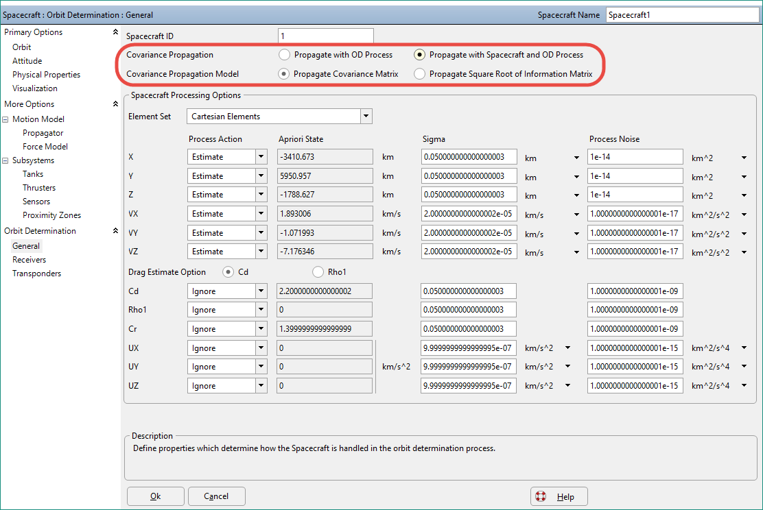
To propagate a Spacecraft's covariance, the Spacecraft must be propagated with an Integrator and Force Model, as opposed to an ephemeris file. To turn on covariance propagation, set the following flag in FreeFlyer script, or use the Covariance Propagation setting in the Spacecraft object editor shown below:
// Turn on Covariance Propagation Spacecraft1.OD.PropagateCovariance = 1; |

You can also control two additional settings for the covariance propagation:
1.CovariancePropagationModel – Choose whether to propagate the covariance matrix or the square root of the information matrix. When a Spacecraft is being estimated using a KalmanFilterOD object, covariance propagation is always done using the full covariance matrix. When using the SquareRootInformationFilterOD object, square root of the information matrix is used. 2.STMCalculationMethod – Choose how the partial derivatives associated with the State Transition Matrix are calculated. There are three possible choices: a.J2 Semi-analytic – This method uses analytic partial derivatives based on the force model of the Spacecraft. The point-mass of all celestial bodies are included, and the J2 term of the Central Body’s gravity potential is also included. This method is faster but less accurate. This method is a second order approximation that is most accurate at a 16 second step-size. b.Numeric – This method uses centrally-differenced numeric partial derivatives for all forces included in the force model of the Spacecraft. The STM partials are computed through a forward Euler approximation. This method is more accurate than the J2 Semi-analytic method, but slower. c.Variational Equations – This method numerically integrates the partial derivatives of the spacecraft accelerations to compute the state transition matrix. Variational Equations is the recommended approach, since this method is faster and more accurate than the Numeric method, and less sensitive to the propagator step size setting. When using the Variational Equations approach for covariance propagation, the partial derivatives of the dynamical model with respect to the estimated state are numerically integrated along with the propagated state.
Note: The STM is calculated at each integration step, rather than being accumulated over a propagation loop. |
Spacecraft1.OD.CovariancePropagationModel = 0; // Propagate Covariance Matrix
(Spacecraft1.Propagator AsType Integrator).STMCalculationMethod = 2; // Use Variational Equations |
Covariance Reference Frames
You also have the ability to set and get the Spacecraft's covariance for the Cartesian element set in any natively supported Attitude Reference Frame, such as International Celestial Reference Frame (ICRF), Radial/In-Track/Cross-Track (RIC), Local Vertical/Local Horizontal (LVLH), Velocity/Normal/Binormal (VNB), Geodetic, UVW, or a Custom Coordinate System through the SpacecraftCovariance Object. Although you are able to set and get the Spacecraft's covariance in different reference frames, the covariance is always stored and used in ICRF. These reference frames provide a more physically intuitive representation of the covariance.
Note: These methods only apply to the Cartesian Element Set for Orbit Determination. This does NOT apply to the TLE and Equinoctial Element sets. When changing Element Sets, by calling SetElementSetToProcess(“Equinoctial”); the covariance is converted between element sets. However, when the Element Set is Cartesian, the Covariance shall remain in ICRF coordinates, but you will be able to Get/Set the covariance in other reference frames as listed above.
Writing the position and velocity covariance is only supported for the CCSDS OEM ephemeris file format.
// Set the covariance of the Spacecraft state in inertial frame, after converting from RIC Matrix ric_cov Spacecraft.OD.Covariance.SetCovarianceInFrame("RIC", ric_cov);
// Get the covariance of the Spacecraft state in the LVLH frame Matrix lvlh_cov; lvlh_cov = Spacecraft.OD.Covariance.GetCovarianceInFrame("LVLH"); |
Covariance Visualization
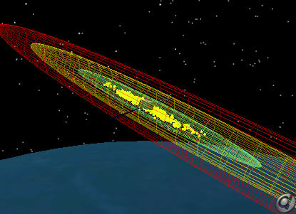
To View the Cartesian position covariance of a Spacecraft as its Error Ellipse requires two simple steps:
1.Add a Proximity Zone to the Spacecraft
2.Calculate the Error Ellipse based on the Cartesian position covariance, and map it into the Proximity Zone. This is done in FreeForm script using the MapErrorEllipsoid method, which is associated with the Covariance object.
Note: The MapErrorEllipsoid method will automatically convert and display the Cartesian position covariance independent of the element set used to specify the covariance. |
// Map 1, 2, and 3 sigma Covariance error ellipsoids to Proximity Zones Spacecraft1.OD.Covariance.MapErrorEllipsoid(Spacecraft1.ProximityZones[0], 1); Spacecraft1.OD.Covariance.MapErrorEllipsoid(Spacecraft1.ProximityZones[1], 2); Spacecraft1.OD.Covariance.MapErrorEllipsoid(Spacecraft1.ProximityZones[2], 3); |
The Spacecraft Covariance Propagation Sample Mission Plan demonstrates this functionality.

Spacecraft with 1, 2, and 3 Sigma Error Ellipsoids