These sample Mission Plans demonstrate the various FreeFlyer objects used for Orbit Determination, using both Batch Least Squares estimation and the Kalman Filter, as well as the generation and editing of tracking data. After exploring these Mission Plans, continue to the Orbit_Determination Guide for more information.
Note: The deprecated Orbit Determination system from FreeFlyer 6.5 and earlier is not available in versions of FreeFlyer 6.10 and higher.
Jump to a Mission Plan Description:
BatchLeastSquaresOD - FFGroundObservation - GUI
This MissionPlan demonstrates how FreeFlyer can be used to perform Orbit Determination using Batch Least Squares to process Ground Network (GN) measurements of Range, Range Rate, Azimuth, and Elevation data. In this example, the Batch Least Squares object is created and configured using FreeFlyer's Object Browser.
The data processed in this MissionPlan was generated with the GenerateTrackingData MissionPlan. The initial state of the LEO spacecraft is perturbed from the truth orbit by about 500 meters in each axis in position.

Plot of RMS values over 5 iterations of a Batch Least Squares estimation process
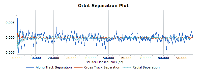
BatchLeastSquaresOD - FFGroundObservation - Script
This MissionPlan demonstrates how FreeFlyer can be used to perform Orbit Determination using Batch Least Squares to process Ground Network (GN) measurements of Range, Range Rate, Azimuth, and Elevation data. In this example, the Batch Least Squares object is created and configured using FreeFlyer's FreeForm scripting.
The data processed in this Mission Plan was generated with the GenerateTrackingData Mission Plan. The initial state of the LEO spacecraft is perturbed from the truth orbit by about 500 meters in each axis in position.

Orbit Separations between Truth and Estimated spacecraft states after 5 iterations of a Batch
BatchLeastSquaresOD - In a Loop
This MissionPlan demonstrates how FreeFlyer can be used to perform Orbit Determination using Batch Least Squares to process Ground Network (GN) measurements of Range, Range Rate, Azimuth, and Elevation data.
In this example, the Batch Least Squares object is used to process a 1-day span of Ground Network (GN) measurements of Range, Range Rate, Azimuth, and Elevation data four separate times. Each time the Batch is processed, a different Solution Epoch is chosen using all four of FreeFlyer's options. Also, for Solutions 2 and 4, Tropospheric modeling is turned off.
BatchLeastSquaresOD - Lunar FFGroundObservation Simulate And Process
This Mission Plan demonstrates how to use FreeFlyer to simulate GroundStation tracking data for a Lunar orbit and process it in the BatchLeastSquaresOD object. The lunar orbit shown here is edge-on towards the Earth, creating an observability problem; due to a lack of geometric diversity, the BatchLeastSquaresOD solution has difficulty resolving the cross-track position of the spacecraft. The results can be seen in the solution covariance as the EstimatedSC is propagated around the orbit along with the TruthSC.

View of ground observation being simulated using a Truth state
BatchLeastSquaresOD - Maneuver Estimation - FFGroundObservation - Simulate And Process
This Mission Plan demonstrates how to perform Maneuver Estimation in FreeFlyer. The Thruster attached to the Truth Spacecraft has a thrust of 4.4 N. The a priori estimate for the thruster attached to the Estimated Spacecraft is 5.5 N. The Batch Least Squares estimates the Thrust Scale Factor of a Finite Burn in order to compensate for this difference.

Estimated Thrust Scale Factor for a Finite Burn
BatchLeastSquaresOD - CustomObservation - Comparison to PointSolutionObservation
This Mission Plan demonstrates how to utilize Custom Observations by implementing the GNSS Point Solution measurement model as a Custom Observation. The Mission Plan simulates one set of Point Solution measurements and processes them using both the built-in PointSolutionObservation and new CustomObservation objects. Each set of observations is processed in a separate Batch Least Squares estimator and the results are compared. This Mission Plan outputs three different plots, comparing the native and custom Total Position Residuals Pre- and Post-Update, a plot comparing the native and custom Solution Estimated Biases, and a plot comparing the solution Range Errors. Lastly, the Mission Plan Reports the percent change, native batch least square root mean square and custom batch least square root mean square for each iteration.

Plot Comparing the Position Residuals Pre- and Post-Update from CustomObservation and PointSolutionObservation
CCSDS Ephemeris With CovarianceInFrame
This Mission Plan demonstrates users’ ability to set the Spacecraft’s covariance in reference frames other than ICRF, these reference frames include RIC, LVLH, VNB, UVW, Geodetic, and a Custom Coordinate System. This Mission Plan also generates two CCSDS Ephemerides with covariance. When calling the SetCovarianceInFrame Method, it takes the reference frame of the specified input, converts it into ICRF, and sets it into the Spacecraft covariance.

3D View of a Spacecraft with covariance in the LVLH Frame
Covariance Propagation Comparison
This Mission Plan compares the three different covariance propagation methods available to FreeFlyer.
1.J2 Semi-analytic 2.Numeric 3.Variational Equations |
The differences in the sigma values are displayed in a Plot over time. The differences in the run times are also displayed at the termination of the Mission Plan.

Differences in the X-sigma between the three different covariance propagation methods
Draw Random States From Covariance
This Mission Plan demonstrates how to generate random position and velocity states using a Gaussian distribution. Monte Carlo runs are used to simulate these states, which are stored in a Formation object. A ProximityZone is created around the Spacecraft to check how many states fall within a defined distance. States inside the ProximityZone are colored red, and states outside are colored green. The Mission Plan tracks the percentage of states inside the zone and plots this percentage over time. The ProximityZone size is based on a k-sigma value of k = 3.763, meaning about 99.7% of the states are expected to fall within the zone. At the end of the Mission Plan, the actual percentage is calculated to verify this expectation.

Plot of the percent of states in range of the ProximityZone
Estimation with Different Element Sets
This Mission Plan demonstrates how to process a Point Solution in both the Cartesian and Equinoctial element sets using a Kalman Filter. The only difference between the states are the element sets being used to process the covariance.

Plot of the orbit separations between a spacecraft being processed in the Cartesian element set and another in the Equinoctial element set
Generate TwoLineElement from Ephemeris
This Mission Plan demonstrates how FreeFlyer can be used to generate a Two-Line Element file using the SGP4StateEstimator. In this example, the SGP4 state is estimated from a definitive spacecraft using an ephemeris propagator.

Output TLE when generated through the use of a propagator
Generate TwoLineElement from Tracking Data
This Mission Plan demonstrates how FreeFlyer can be used to generate a Two-Line Element file using the SGP4StateEstimator. In this example, the SGP4 state is estimated using ground station observation data. The initial state of the spacecraft is perturbed from the definitive orbit by 1 km in each axis in position.

2D View of Spacecraft and GroundStation objects used to generate the TLE
This Mission Plan demonstrates how to use FreeFlyer to generate different types of tracking data. The user has the option to generate Ground Station, GPS Pivot Point Solution, BlackJack Point Solution, or GPS Pseudorange data. The data generated by this Mission Plan can be processed with FreeFlyer's Kalman Filter or Batch Least Squares orbit determination processes, and can be used as input to the KalmanOD or BatchOD Sample Mission Plans.

2D View of Spacecraft and GroundStation objects used to generate tracking data
Get CovarianceInFrame And ProcessNoise
This Mission Plan demonstrates the ability to set the process noise and set, get the covariance matrix and state sigmas in frames other than ICRF. These reference frames include RIC, LVLH, VNB, UVW, Geodetic, and Custom Coordinate System. This Mission Plan provides the process noise and covariance matrix in different attitude reference frames to then be converted in the inertial reference frame. It returns the covariance of the spacecraft state in the specified attitude reference frame.

Reported Spacecraft State Sigmas and Covariance Matrix in the specified frame
Initial Orbit Determination
This Mission Plan demonstrates the use of FreeFlyer for initial orbit determination. The user chooses a preliminary OD algorithm (Site-Track, Gibbs, Herrick-Gibbs, Angles Only Gauss, Angles Only Double R, or Lambert's algorithm using Battin's method) and chooses whether to use sample data or input their own data. Depending on the user selections, the specified data will be processed in the chosen algorithm, the resulting orbit will be visualized, and the orbital elements will be reported to the screen.

Orbit calculated using the Gibbs algorithm for initial Orbit Determination
KalmanFilterOD - Choose Tracking Data File
This Mission Plan demonstrates how FreeFlyer® can be used to perform Orbit Determination using a Kalman Filter to process Ground Network (GN) measurements of Range, Range Rate, Azimuth, and Elevation data.
In this example, a custom user interface is used to choose between different tracking data files. The options vary between one and three different GroundStations and one to three days of propagation.
The data processed in this Mission Plan was generated with the GenerateTrackingData Mission Plan. The initial state of the LEO spacecraft is perturbed from the truth orbit by about 500 meters in each axis in position.
User interface used to choose different tracking data files
KalmanFilterOD - Consider Analysis
This Mission Plan demonstrates how FreeFlyer can be used to perform a simple Covariance Analysis using a Kalman Filter to process Ground Network (GN) measurements of Range, Range Rate, Azimuth, and Elevation data. In this example, the Kalman Filter object is configured to Consider the ConsiderSC's position, velocity, and Cd. The data processed in this Mission Plan was generated with the GenerateTrackingData Mission Plan.

View of a Spacecraft being considered in a Kalman OD process, with a tracking GroundStation in the background
KalmanFilterOD - CustomObservation - Comparison to PointSolutionObservation
This Mission Plan demonstrates how to utilize custom observations by implementing the GNSS Point Solution measurement model as a custom observation. The Mission Plan simulates one set of Point Solution measurements and processes them using both the built-in PointSolutionObservation and new CustomObservation objects. Each set of observations is processed in a separate Extended Kalman Filter estimator and the results are compared. This Mission Plan outputs three different plots, comparing the native and custom Total Position Residuals Pre- and Post-Update, a plot comparing the native and custom Solution Estimated Biases, and a plot comparing the solution Range Errors. Lastly, the Mission Plan Reports the percent change, native batch least square root mean square and custom batch least square root mean square for each iteration.

Plot Comparing the Position Residuals Pre- and Post-Update from CustomObservation and PointSolutionObservation
KalmanFilterOD - FFGroundObservation - GUI
This Mission Plan demonstrates how FreeFlyer can be used to perform Orbit Determination using a Kalman Filter to process Ground Network (GN) measurements of Range, Range Rate, Azimuth, and Elevation data.
In this example, the Kalman Filter object is created and configured using FreeFlyer's Object Browser. The data processed in this Mission Plan was generated with the GenerateTrackingData Mission Plan. The initial state of the LEO spacecraft is perturbed from the truth orbit by about 500 meters in each axis in position.

Plot of the separations of Truth and Estimated states. In this example the filter is stepped using the filter step size.
KalmanFilterOD - FFGroundObservation - Script
This Mission Plan demonstrates how FreeFlyer can be used to perform Orbit Determination using a Kalman Filter to process Ground Network (GN) measurements of Range, Range Rate, Azimuth, and Elevation data.
In this example, the Kalman Filter object is created and configured using FreeFlyer's FreeForm scripting. The data processed in this Mission Plan was generated with the GenerateTrackingData Mission Plan. The initial state of the LEO spacecraft is perturbed from the truth orbit by about 500 meters in each axis in position.

Plot of the separations of Truth and Estimated states. In this example the filter is stepped to each observation epoch.
KalmanFilterOD - Multi-Spacecraft Simulation and Filtering
This Mission Plan demonstrates how to process multiple Spacecraft in a single instance of the KalmanFilterOD object. There is one Spacecraft in a LEO that is being tracked by two TDRS Spacecraft. Each TDRS Spacecraft is being tracked by two GroundStations. TDRS Two-way Range and Two-way Doppler measurements are simulated for the LEO Spacecraft and GroundStation Range measurements are simulated for each TDRS Spacecraft. The GroundStation Range measurements are only simulated when TDRS Observations are not being simulated.
All the Observations are then processed in one KalmanFilterOD object. The filter state has a dimension of 24, and consists of the following:
•LEO Spacecraft oPosition oVelocity oCd oTransponder Delay
•TDRS Spacecraft (both) oPosition oVelocity oCr oTransponder Delay |
Finally, the orbit errors, measurement residuals, post-update Covariance, Correlation Matrix, and estimated Transponder Delays are shown.
")
Plot showing radial, in-track, and cross-track separations between simulated and estimated spacecraft (1 LEO and 2 TDRS)
KalmanFilterOD - Point Solution Simulation and Filtering
This Mission Plan demonstrates how to use the FreeFlyer Orbit Determination system to simulate and filter data simultaneously. A 'truth' spacecraft is used to simulate data, which is populated into a Point Solution Observation. That observation is then processed using a second spacecraft and a Kalman Filter. The second spacecraft has been offset from the truth spacecraft by 1 km/s in each direction for position.
The output shows a plot of the diagonal of the covariance matrix, the post-update residuals, and the separation of the two spacecraft. In the 3D View, the two spacecraft are shown along with the 3-sigma error ellipsoid.
KalmanFilterOD - Pseudorange Point Solution Comparison
This Mission Plan demonstrates how to process both Point Solution and Pseudorange tracking data using a single Kalman Filter. These states were calculated by applying a 0.75 km offset in position to the first states in the Point Solution data file. The resulting orbit separations, sigmas, and residuals are shown.

Orbit trace comparison of 2 Spacecraft being estimated using Pseudorange and PointSolution data
KalmanFilterOD - Spacecraft Observation Simulation and Filtering
This Mission Plan demonstrates the use of the FreeFlyer Orbit Determination system to process Spacecraft-to-Spacecraft tracking data. There are two spacecraft in similar Geostationary orbits, and one spacecraft is in view of a Sensor on-board the other. Four measurements are simulated, Range, Range-Rate, Azimuth, and Elevation. Azimuth and Elevation are computed relative to the reference frame of the observing Sensor. The SC-to-SC observations are processed using FreeFlyer's Kalman Filter and the position and velocity of the target spacecraft are estimated. The orbit errors of the target spacecraft are shown as line-of-sight and range errors.
Kalman Filter - TDRS Simulation and Filtering
This Mission Plan demonstrates how to simulate and filter TDRS Observations all in one loop. There is one Spacecraft in a LEO, and two TDRS Spacecraft, each with a dedicated GroundStation. TDRS Two-way Range and Two-way Doppler measurements are simulated using the SimulateTrackingData method. Then the Observations are processed using different measurement noise, bias and error settings.
Finally, the orbit errors, measurement residuals, post-update Covariance, and estimated Transponder Delay are shown.

Two-Way Doppler and Range Residuals from White Sands
Monte Carlo Probability Of Collision
This Mission Plan demonstrates FreeFlyer's ability to parse a Conjunction Data Message (CDM), in JSON or KVN format, to calculate the Time of Closest Approach (TCA) and Probability of Collision (Pc) for a conjunction of two spacecraft in Low Earth Orbit (LEO). Then it is used to create 5000 random states drawn from a Gaussian distribution in the equinoctial state space of the two spacecraft to recalculate the Probability of Collision using a Monte Carlo Simulation. The differences between the two simulations are then reported out for comparison.

Plots of the variance in TCA and Probability of Collision.
KalmanSmoother - Pseudorange
This Mission Plan demonstrates the use of a Kalman Filter with a Smoother. The Smoother in this example is configured as a Fixed Lag smoother. First, an initial truth state obtained from an ephemeris is altered slightly and processed in a Kalman Filter for about half a day. At the end of the filtering, the smoothed solution is copied into a second spacecraft. The smoothed solution and the filtered solution are propagated back to the start of the truth ephemeris, and then propagated all three spacecraft (truth, filtered, and smoothed) are propagated forward in time. The differences in SMA and range between the three spacecraft are then plotted.

View of Truth, Filtered, and Smoothed Spacecraft Orbits
Spacecraft Covariance Propagation
This Mission Plan demonstrates how to propagate a Spacecraft's Covariance (without performing Orbit Determination). The Covariance is visualized by mapping the 1, 2, and 3-sigma error ellipsoids to color-coded Proximity Zones centered on the Spacecraft.
The visualization also includes a Formation of Spacecraft whose states have been initialized by applying Gaussian Noise to the state of Spacecraft1. As the formation is propagated we can see that the majority of the states stay within the 1-sigma ellipse.

Spacecraft with 1, 2, and 3 Sigma Error Ellipsoids
SquareRootInformationFilterOD - FFGroundObservation - GUI
This Mission Plan demonstrates how FreeFlyer can be used to perform Orbit Determination using a Square Root Information Filter to process Ground Network (GN) measurements of Range, Range Rate, Azimuth, and Elevation data.
In this example, the SquareRootInformationFilterOD object is created and configured using FreeFlyer's Object Browser. The data processed in this Mission Plan was generated with the GenerateTrackingData Mission Plan. The initial state of the LEO spacecraft is perturbed from the truth orbit by about 500 meters in each axis in position.
Plot of the separations of Truth and Estimated states. In this example the filter is stepped using the filter step size.
SquareRootInformationFilterOD - FFGroundObservation - Script
This Mission Plan demonstrates how FreeFlyer can be used to perform Orbit Determination using a Square Root Information Filter to process Ground Network (GN) measurements of Range, Range Rate, Azimuth, and Elevation data.
In this example, the SquareRootInformationFilterOD object is created and configured using FreeFlyer's scripting language. The data processed in this Mission Plan was generated with the GenerateTrackingData Mission Plan. The initial state of the LEO spacecraft is perturbed from the truth orbit by about 500 meters in each axis in position.
Plot of the separations of Truth and Estimated states. In this example the filter is stepped to each observation epoch.
SquareRootInformationFilterOD - GPSGalileo - Simulation And Filtering
This Mission Plan demonstrates the use of the FreeFlyer Orbit Determination system to simulate GNSS Pseudorange tracking data and process it as Iono-Free Pseudoranges. Data is simulated and processed for both the GPS and Galileo navigation systems. The data is processed with a Square-Root Information Filter (SRIF), and orbit errors, uncertainties, post-update residuals, and time bias estimates are plotted.
The wide view shows both navigation constellations and the Geosynchronous transfer orbit of the spacecraft being estimated. The color-coded vectors indicate which GNSS satellites are generating observation data.

GNSS Pseudorange Simulation and Processing
Tracking Data Editor - GroundObservation Data
This MissionPlan demonstrates how FreeFlyer can be used to edit FFGroundObservation tracking data files before they are used in an Orbit Determination process (either Kalman Filter or Batch Least Squares).
The input file was generated with the Generate Tracking Data sample Mission Plan. When the TrackingDataEditor Object is shown, the user is able to view the data in the file in a graphical format. Either the measurements or the residual data can be plotted.
The 'Mark as Invalid' button can be used to flag any outlying data for exclusion from the new output file. When the users selects 'Save and Continue', the edited file will be generated and sent to the specified output path.
![]()
TrackingDataEditor - GroundObservation Data - Configure in Script
This MissionPlan demonstrates how FreeFlyer can be used to edit FFGroundObservation tracking data files before they are used in an Orbit Determination process.
The UserInterface allows the user to configure the TrackingDataEditor Object in FreeForm script. Either the measurements or the residual data can be plotted.
The input file was generated with the Generate Tracking Data sample Mission Plan. When the TrackingDataEditor is shown, the user is able to view the data in the file in a graphical format.
The 'Mark as Invalid' button can be used to flag any outlying data for exclusion from the new output file. When the users selects 'Save and Continue', the edited file will be generated and sent to the specified output path.
![]()
TrackingDataEditor - List Of GroundObservations
This MissionPlan demonstrates how FreeFlyer can be used to simulate FFGroundObservations and edit the data using the TrackingDataEditor. The input data for the TrackingDataEditor was generated using a List of FFGroundObservations. When the TrackingDataEditor Object is shown, the user is able to view the data in the file in a graphical format.
The 'Mark as Invalid' button can be used to flag any outlying data for exclusion from the output file. When the users selects 'Save and Continue', the output file will be generated and sent to the specified output path.
TrackingDataEditor - PointSolution Data
This MissionPlan demonstrates how FreeFlyer can be used to edit Black Jack Point Solution tracking data files before they are used in an Orbit Determination process (either Kalman Filter or Batch Least Squares). When the TrackingDataEditor Object is shown, the user is able to view the data in the file in a graphical format. Either the measurements or the residual data can be plotted.
The 'Mark as Invalid' button can be used to flag any outlying data for exclusion from the new output file. The valid data is written to a FFGroundObservationFile.
TrackingDataEditor - Pseudorange Data
This MissionPlan demonstrates how FreeFlyer can be used to edit RINEX Pseudorange tracking data files before they are used in an Orbit Determination process (either Kalman Filter or Batch Least Squares). When the TrackingDataEditor Object is shown, the user is able to view the data in the file in a graphical format. Either the measurements or the residual data can be plotted.
The 'Mark as Invalid' button can be used to flag any outlying data for exclusion from the new output file. When the users selects 'Save and Continue', the edited file will be generated and sent to the specified output path.
UnscentedKalmanFilterOD - Spacecraft Observation Simulation and Filtering
This Mission Plan demonstrates the use of the FreeFlyer Orbit Determination system to process Spacecraft-to-Spacecraft tracking data. There are two spacecraft in similar Geostationary orbits, and one spacecraft is in view of a Sensor on-board the other. Four measurements are simulated, Range, Range-Rate, Azimuth, and Elevation. Azimuth and Elevation are computed relative to the reference frame of the observing Sensor. The SC-to-SC observations are processed using FreeFlyer's Unscented Kalman Filter and the position and velocity of the target spacecraft are estimated. The orbit errors of the target spacecraft are shown as line-of-sight and range errors.