Nathan Griffith
A Letter from Dr. Nathan Griffith, Senior Space Products Software Engineer
Hi FreeFlyer Users! My name is Dr. Nathan Griffith, Senior Space Products Software, and during the past year it’s been my pleasure to expand the capabilities of FreeFlyer 7.10 into the realm of optical communications.
In addition to having a PhD in cosmic ray physics, in my free time I’m also an amateur radio operator and astrophotographer, a set of interests that I was thrilled to realize were all relevant to the background research for this feature!

In the 2010s and 2020s, on-orbit optical communications has moved from the realm of technology demonstrations and into practical implementation. And it’s easy to see why, since its very short wavelengths offer the following advantages over traditional radio frequency (RF) communications:
- Reduced size, weight, and power
- Comparable or better data rates compared to RF
- Better physical security, owing to a narrow beam spot at ground level which is more difficult to intercept
So for the correct application, moving to optical communications from RF can truly allow you to achieve more with less.
But what are some challenges associated with optical comms?
When answering this question, it’s useful to consider a mathematical expression called the “link margin,” which consists of “gains” (which make the connection easier to close), and “losses” (which make it harder to close). The link margin can be thought of as a sum, where each term is a gain (positive) or a loss (negative), followed by a subtraction of the receiver sensitivity. If the link margin is positive, your link is achievable at the performance level you’ve indicated, but if it’s negative, you’ll have to find some way to make up the difference.
In an optical link the gains are provided by the:
- Transmitter (think of the narrow beam of a laser pointer, it’s this intense focus that makes a lot of the “magic” of optical comms possible)
- Receiver (this is basically a telescope, and the diameter of it sets the gain)
For losses we have free space loss, which is unavoidable and the same as in RF comms, but we also have a number of atmospheric effects that we must now take into account. These consist of:
- Atmospheric absorption (not modeled in FreeFlyer, but can be disregarded if we choose a wavelength which falls within one of the transparent “windows” of Earth’s atmosphere; 1550 nm is a very popular choice)
- Atmospheric scattering (modeled in FreeFlyer by a straightforward parameterization using widely available meteorological visibility measurements)
- Atmospheric scintillation (modeled in FreeFlyer via a turbulence path integral; this a signal “wobble” caused by pockets of warm air in the atmosphere, it’s also what makes my planet pictures blurry!)
On the receiver side, sensitivity is set by the type of technology the receiver employs, along with some figures from its spec sheet. One popular choice of receiver is the avalanche photodiode (APD) type, which uses a light-to-current conversion process similar to one employed in my cosmic ray studies. There are lots of other receiver types though, and FreeFlyer provides physical models for hetero/homodyne and preamplified varieties as well.
Oh, and before I forget! Another important source of loss is the mechanical precision of the component which points your laser transmitter. As you might imagine, the narrower you make your laser beam, the more precise your pointing must be, so I’ve made sure to model this important tradeoff in FreeFlyer as well.
As you can see there are quite a large number of parameters that go into considering the performance of an optical comms system, so FreeFlyer gives you the ability to either flexibly represent your current system, or sketch out a new one which meets your needs, all the way from site selection, to topics we haven’t even talked about yet like modulation choice.
It’s been a real a thrill to work on this feature, and I can’t wait to see what you do with it! To help you get acquainted with all the new elements related to optical communication simulation, FreeFlyer 7.10 comes with a number of sample mission plans that show off various capabilities. These include:
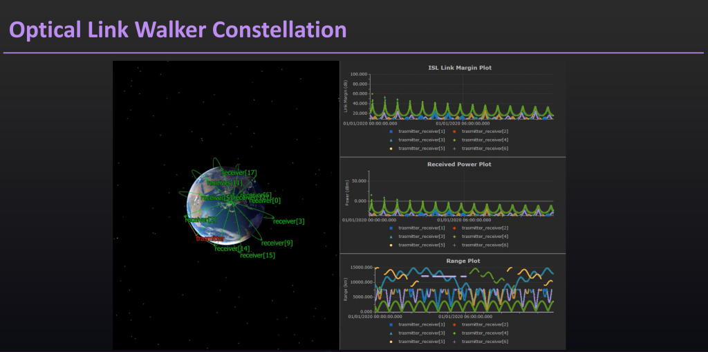
1.) A model of a walker constellation employing optical links between satellites

2.) A scenario exploring the effect of different modulation choices on an optical link between a lunar lander and a ground station on Earth
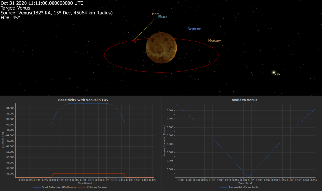
3.) An example of how the presence of a bright celestial object (e.g. Venus) in the field of view of can degrade optical receiver sensitivity


