The Terrain object can be added to a Mission Plan for use in the visualization and analysis of terrain features with Spacecraft and GroundVehicle objects. This object can be used to load high-resolution terrain data files of specific areas of interest or of the entire globe to determine line-of-sight visibility between any two objects orbiting in space, stationary anywhere, or moving on the ground. Once the terrain data has been loaded, users can query the elevation at a specified latitude and longitude contained within the data file.
The Terrain object also allows a user to visualize and perform a viewshed analysis or determine the viewshed experienced over a period of time. When performing viewshed analyses with the Terrain object, a user has the ability to model any number of any type of observers (Spacecraft, GroundVehicle, or GroundStation objects) to create a single-observer viewshed or a combined viewshed that takes all objects visibility into account. If a GroundVehicle is used with the Terrain object, a user could set it to use waypoints or a heading and have it automatically follow the terrain elevation.
The following Sample Mission Plans (included with your FreeFlyer installation) demonstrate the use of the Terrain object:
|
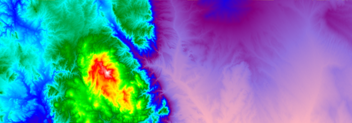
Terrain Visualzation using a PointGroup
Using the Terrain Object
A Terrain object can be defined by using the Terrain object editor or through FreeFlyer script. When defining the Terrain object, it will require terrain data to be loaded using one of the approved terrain data file formats that has already been processed by the Terrain Index Generator. The different approaches are covered below.
Defining Terrain with the Object Editor
To define the Terrain object within the object browser, you will use the Terrain object editor. The Terrain object editor contains a properties page that allows you to load any number of Terrain Data Files, also known as raster files.
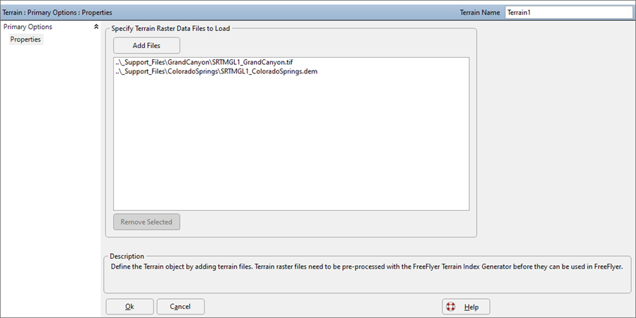
Terrain Object Editor
Defining Terrain with FreeFlyer Script
The Terrain object can also be created using the FreeForm script editor. To define a Terrain object in FreeFlyer script, specify the terrain data file path(s) or directory as shown in the example below.
Terrain myTerrain;
// Three different options for adding terrain data to a Terrain object follow myTerrain.AddFiles("Colorado_1.tif"); // Add individual terrain data files myTerrain.AddFiles("Colorado_1.tif", "Colorado_2.tif"); // Add multiple terrain data files myTerrain.AddFilesInDirectory("C:\Data\GTOPO30\", ".tif"); // Add all TIF terrain data files in a directory at once |
Adding Terrain to a VisibilitySegment
The Terrain object can be added to or removed from a VisibilitySegment in order to define the surface features that will be considered when determining if the observer can see the target. The VisibilitySegment also allows a user to compute and visualize a viewshed, by configuring a PointGroup that represents the target points. When including occulting terrain the user must model occulting bodies as ellipsoids using the VisibilitySegment.CelestialObjectOccultationModel property, as shown below.
Terrain Terrain1; Terrain Terrain2; VisibilitySegment Segment;
Segment.SetObserver(GroundVehicle1); Segment.SetTarget(Spacecraft1);
Segment.AddOccultingTerrain(Terrain1, Terrain2); Segment.RemoveOccultingTerrain(Terrain2); Segment.CelestialObjectOccultationModel = 1; // Ellipsoid |
Terrain Data
Terrain data is typically represented as a collection of data files or “tiles”. Individual tiles can cover a relatively small area, such as 1° by 1° of latitude/longitude. The most common terrain data file formats are GEOTiff, which are specialized image files encoded with elevation data, and binary Digital Terrain Elevation Data (DTED). Three of the most popular and complete terrain data sets are listed below at a high level, while even further information about these sets can be found on the Terrain Data Files page.
All terrain data to be used with the Terrain object must be pre-processed using the Terrain Index Generator command line utility. When generating terrain index files using the Terrain Index Generator utility, you have the ability to specify the vertical datum as EGM96 or WGS84. See the above-linked page for that application to get more information on what it does, how to use it, and why it's necessary.
Source |
Coverage |
Resolutions |
|---|---|---|
Global |
30 arc-seconds (approximately 1 kilometer) |
|
SRTM (Shuttle Radar Topography Mission) |
Global *Only -60 deg to 60 deg Latitude |
3 arc-seconds (approximately 90 meters) 1 arc-second (approximately 30 meters) |
NED (National Elevation Dataset) |
United States |
1 arc-second (approx. 30 meters) 1/3 arc-second (approx. 10 meters) 1/9 arc-second (approx. 3 meters) *In Limited Areas |
Note: The Terrain object only supports Earth-based terrain tiles at this time.
Raster Data
Rasters are digital aerial photographs, imagery from satellites, digital pictures, or even scanned maps. Geographic information systems (GIS) data is commonly stored in a raster format to encode geographic data as the pixel values. Rasters are well suited for representing data that changes continuously across a surface, such as with topography. The raster data below displays elevation using blue to show lower elevation and green, yellow, and red shading to show higher elevations.
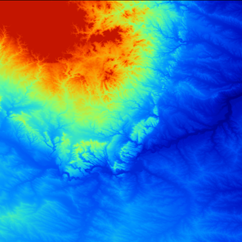
Raster Data for Mount Rushmore
Terrain Index Files
The purpose of the FreeFlyer terrain index file is to help increase query performance when evaluating line-of-sight calculations involving Terrain using a VisibilitySegment object. At runtime, FreeFlyer will check for a corresponding terrain index file to an accessed terrain file by searching the same directory for the terrain's same filename but with an .ffidx suffix. If there is no corresponding terrain index file to the accessed terrain data, FreeFlyer will throw a runtime error. This error can be resolved by simply using the Terrain Index Generator utility to create an appropriate terrain index file.
Note: Terrain data and index files must be locally accessible. Each time terrain data is queried for terrain height or a terrain index is queried for a line-of-sight intersection, there are multiple reads that are made to the disk. It is possible to access this data over a network share, but any additional network-induced latency could potentially degrade FreeFlyer’s performance.
Terrain Data Interpolation
The Terrain object will use double-linear interpolation when querying a height located between two data points in a raster file and when determining line-of-sight intersections with terrain. This is accomplished by computing the height of a point as the average from four corners that use individual pixels contained within the terrain raster file. This is demonstrated in the image below where FreeFlyer uses double-linear interpolation to form the four triangles and visualize them with a PointGroup.
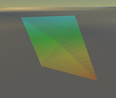
Four triangles Terrain Double-linear Interpolation Method
Example: Determining Height at a Latitude/Longitude
In this example, the height at a specific Latitude/Longitude is reported.
Terrain Terrain1;
Terrain1.AddFiles(".\Mt_Rushmore.tif");
// Report the Height for Abe Lincoln's Face on Mount Rushmore Report Terrain1.GetHeight(43.8791, -103.4591) // km |
Example: Set/Get GroundStation Height using Terrain
In this example, the height for a GroundStation is set and reported using the Terrain object. This example sets the GroundStation height at 3 meters above the Terrain height using the GroundStation.SetHeight() method to prevent erroneous visibility evaluations.
Terrain Terrain1;
Terrain1.AddFiles(".\Lanham_MD.tif");
GroundStation GroundStation1;
GroundStation1.Latitude = 38.951; GroundStation1.Longitude = -76.834;
// Set GroundStation Height at 3 meters above the Terrain object surface GroundStation1.SetHeight(0.003, Terrain1);
Report GroundStation1.Height; // This will report the height above the central body ellipsoid Report GroundStation1.GetHeight(Terrain1); // This will report the height with respect to the Terrain object |
Note: If a user sets an objects height at 0 km with the SetHeight() method, the Visibility could be returned as true or false due to the object being exactly on the border of the occultation.
Example: Propagate GroundVehicle to follow Terrain
In this example, a GroundVehicle object follows a path designated by waypoints and adjust the GroundVehicle height based on the Terrain object. This example sets the GroundVehicle height at 2 meters above the Terrain height using the GroundVehicle.SetHeight() method to prevent erroneous visibility evaluations. After using the GroundVehicle.SetReferenceTerrain() method the GroundVehicle will maintain a constant height with respect to the reference terrain, and will report an error if you try to move the GroundVehicle outside the terrain. To prevent the error you can confirm whether a GroundVehicle's location is within the Terrain data by using the Terrain.ContainsLocation() method.
Terrain Terrain1; GroundVehicle Truck1;
Terrain1.AddFiles("..\_Support_Files\Terrain_Data\SRTM_ColoradoSprings.tif");
// Set GroundVehicle Propagator to use Waypoints Truck1.SetPropagatorType("GroundWaypoints"); Alias gvProp = (Truck1.Propagator AsType GroundWaypoints);
// Define Waypoint Epochs, Latitude, and Longitude TimeSpanArray epochs = {"Jan 01 2020 00:00:00.000".ParseCalendarDate(), "Jan 01 2020 01:00:00.000".ParseCalendarDate(), "Jan 01 2020 02:00:00.000".ParseCalendarDate()}; Array latitudes = { 38.835585 /*City Hall*/, 38.840730 /*Pike's Peak*/, 38.737192 /*Cheyenne Mountain*/}; Array longitudes = {-104.821093 /*City Hall*/, -105.042224 /*Pike's Peak*/, -104.880818 /*Cheyenne Mountain*/};
// Add Waypoints to the GroundVehicle gvProp.AddWaypoints(epochs, latitudes, longitudes); gvProp.StepSize = TimeSpan.FromSeconds(30);
// Initialize the GroundVehicle location Truck1.Latitude = latitudes[0]; Truck1.Longitude = longitudes[0];
// Set GroundVehicle Reference Terrain Truck1.SetReferenceTerrain(Terrain1);
// Set GroundVehicle Height at 2 Meters above the Terrain Truck1.SetHeight(0.002, Terrain1); // (This will maintain a constant height of 2 meters with respect to the Terrain object surface during propagation)
// Propagate Along the Waypoints While (Truck1.ElapsedTime <= TIMESPAN(2 hours));
// Check if the GroundVehicle is within the Terrain Data Bounds If(Terrain1.ContainsLocation(Truck1.Latitude, Truck1.Longitude) != 1); Report "The GroundVehicle's current location is outside of the Terrain data."; Stop; End;
Plot Truck1.Epoch.ConvertToCalendarDate(), Truck1.Height;
Step Truck1;
End; |
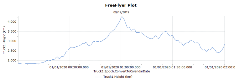
Plot of GroundVehicle height when using a reference Terrain
Example: Determining Visibility between a Spacecraft and GroundStation
In this example, a Terrain object is created to model the Grand Canyon's occultation for a VisibilitySegment between a GroundStation and a Spacecraft. It then plots the contact with and without Terrain occultation included. The GroundStation is located on the floor of a valley with the height set using the Terrain object.
Terrain Terrain1; Spacecraft Spacecraft1; GroundStation GroundStation1;
VisibilitySegment TerrainSegment; VisibilitySegment NonTerrainSegment;
Terrain1.AddFiles("..\_Support_Files\Terrain_Data\SRTM_GrandCanyon.tif");
// Configure Terrain Visibility Segment TerrainSegment.SetObserver(GroundStation1); TerrainSegment.SetTarget(Spacecraft1); TerrainSegment.AddOccultingBody(Earth); TerrainSegment.AddOccultingTerrain(Terrain1); TerrainSegment.CelestialObjectOccultationModel = 1;
// Configure Non-Terrain Visibility Segment NonTerrainSegment.SetObserver(GroundStation1); NonTerrainSegment.SetTarget(Spacecraft1); NonTerrainSegment.AddOccultingBody(Earth); NonTerrainSegment.CelestialObjectOccultationModel = 1;
// Valley Floor in the Grand Canyon GroundStation1.Latitude = 36.1532; GroundStation1.Longitude = -112.1157;
// Set the GroundStation Height from Terrain GroundStation1.Height = Terrain1.GetHeight(GroundStation1.Latitude, GroundStation1.Longitude);
While (Spacecraft1.ElapsedTime < TIMESPAN(3 days));
Step Spacecraft1;
Plot Spacecraft1.EpochText, TerrainSegment.Visibility(Spacecraft1.Epoch); Plot Spacecraft1.EpochText, NonTerrainSegment.Visibility(Spacecraft1.Epoch);
End; |
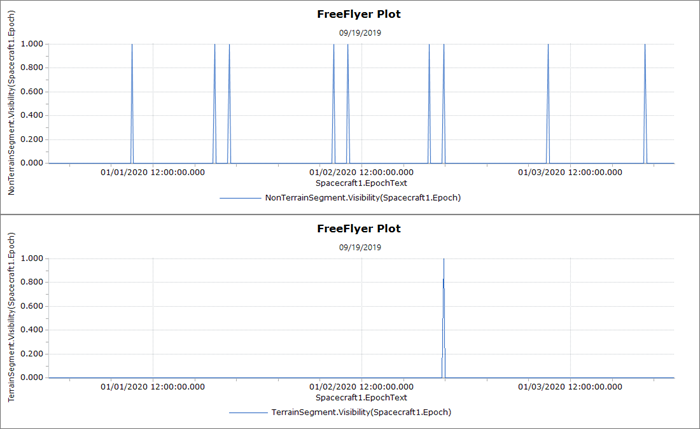
Plot of GroundStation Visibility with and without Terrain occultation
See Also
• Terrain Properties and Methods
•GroundVehicle Guide