A Sensor object can be attached to a Spacecraft or GroundVehicle to evaluate contact times to other Spacecraft, GroundVehicles, GroundStations, Planets, Stars, etc, with respect to the sensor's field of view (FOV). FreeFlyer's Sensor object can be used to model earth sensors, sun sensors, antennas, star trackers or any other instrument with a position, orientation, and field of view.
The FOV of a sensor can be defined as either a cone, a rectangle (slit), or as a series of azimuth and elevation angles (custom mask). An obscuration mask can also be applied to model any blockages in the sensor, such as a solar panel or another instrument that obscures part of the sensor's FOV. The masking is defined by a series of azimuth and elevation angles.
The following Sample Mission Plans (included with your FreeFlyer installation) demonstrate the use of the Sensor object:
|
Defining the Sensor
Sensor Shape
The field of view of a sensor can be defined three ways:
1.Cone Sensor 2.Rectangle (Slit) Sensor 3.Custom Sensor |
Sensor Orientation
The orientation (pointing) of a Sensor boresight can be defined four ways:
1. BoresightUnitVector: Using a unit vector referenced to the Body Coordinate System (BCS) of the Spacecraft 2. BoresightAngles: Using a set of Euler Angles referenced to the Spacecraft BCS. Uses BoresightRotationSeq to define the correct Euler sequence 3. ZAxisAzimuth/ ZAxisElevation: Using a pair of Azimuth-Elevation angles referenced to the Spacecraft BCS
4. Attitude Matrix: Using a Direction-Cosine-Matrix (DCM) referenced to the Spacecraft BCS 5. SetOrientation: Using the mySensor.SetOrientation(CoordinateSystem) method if the Spacecraft AttitudeRefFrame is set to ICRF
|
Defining Obscurations
An obscuration mask can also be applied to each sensor to model any blockages of the FOV. Obscurations can be anything that may block the view of the sensor such as solar arrays, other instruments, or even the Spacecraft body. The obscuration's shape can be configured as a cone, rectangle, or a custom shape. The orientation of the obscuration can be set via a unit vector, Euler angles, a pair of Azimuth-Elevation angles, or an attitude matrix (DCM).
Sensor Position
The Sensor position is defined by x, y, z vector components in the BCS with origin at the Spacecraft Body Center.
Sensor Visualization
The sensor can be any color. The length of the sensor in the 3D View is defined by the Projection Height in units of kilometers.
Spacecraft1.Sensors[0].Color = ColorTools.Yellow; Spacecraft1.Sensors[0].ProjectionHeight = 1000; |
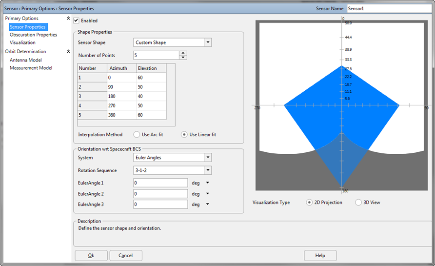
The example below displays a sensor created through the Object Editor, with a linear fit connecting the specified azimuth-elevation points, and an obscuration blocking part of its FOV.

Custom Sensor with Obscuration Mask
Sensor Views
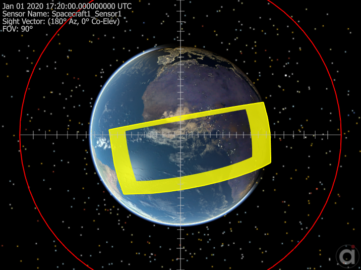
Sensor Views allow users to configure an output window displaying the desired objects in a view looking down the boresight of a Sensor. In the image below, a Sensor View is used to visually confirm access to a Region on the Earth, shown in yellow.

3D Sensor View
Example 1: Cone Sensor
To add a Sensor to a Spacecraft via FreeFlyer script, use the Spacecraft.AddSensor() method. You can also use the Attach command. In this example, the cone half angle, display color, and pointing angle of "sensor1" are edited.
Spacecraft1.AddSensor("sensor1"); Spacecraft1.Sensors[0].Color = ColorTools.Red; Spacecraft1.Sensors[0].ConeHalfAngle = 45; Spacecraft1.Sensors[0].BoresightUnitVector[0] = 1; Spacecraft1.Sensors[0].BoresightUnitVector[1] = 0; Spacecraft1.Sensors[0].BoresightUnitVector[2] = 0; |
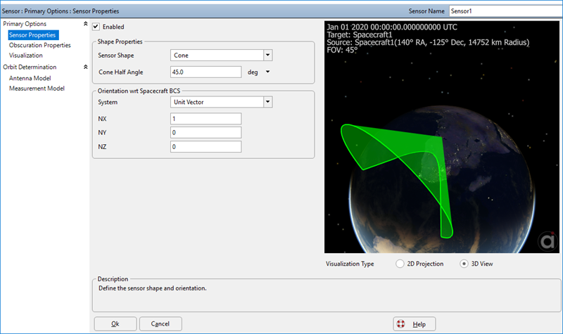
A Sensor can also be created through the Spacecraft object editor. The next image shows a 45-degree conical FOV sensor (pointing down the Spacecraft X-axis) in the preview window of the object editor.

Cone Sensor with 45-degree half angle
Example 2: Custom Sensor
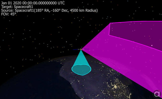
The following example defines two sensors: a rectangular (slit) sensor with a forward angle of 10 degrees, and a side angle of 60 degrees, pointing along the negative y-axis of the spacecraft; and a custom "heart-shaped" sensor defined by a series of 7 Azimuth-Elevation angles.
Spacecraft1.AddSensor("sensor2"); Spacecraft1.Sensors[1].MaskType = 3; Spacecraft1.Sensors[1].Color = ColorTools.Magenta; Spacecraft1.Sensors[1].RectangularHalfAngles = {10, 60}; Spacecraft1.Sensors[1].BoresightRotationSeq = {3, 1, 2}; Spacecraft1.Sensors[1].BoresightAngles = {-90, 0, 90};
Spacecraft1.AddSensor("sensor3"); Spacecraft1.Sensors[2].Color = ColorTools.Cyan; Spacecraft1.Sensors[2].MaskType = 2; // custom shape Spacecraft1.Sensors[2].InterpolationMode = 0; Spacecraft1.Sensors[2].BoresightMaskPoints = 7; Spacecraft1.Sensors[2].BoresightAzimuth = {0, 60, 120, 180, 240, 300, 360}; Spacecraft1.Sensors[2].BoresightElevation = {50, 60, 70, 80, 70, 60, 50};
View Spacecraft1; |

Spacecraft with two Sensors
Example 3: Determining Visibility from a Sensor
The VisibilitySegment.Visibility() method returns a flag that indicates whether there is visibility from an observer to a target. The VisibilitySegment object allows Spacecraft, Sensors, GroundStations or GroundVehicles to be the observer, and Spacecraft, Sensors, GroundStations, GroundVehicles, CelestialObjects, Stars, or PointGroupPoints can be the target. The VisibilitySegment also allows the user to report the azimuth and elevation of the target in the reference frame of the observer. See VisibilityCalculators for more information. For a summary of the coverage and contact output methods in FreeFlyer organized by observer and target object type, see the Contact Method Summary.
VisibilitySegment Segment;
Segment.SetObserver(Spacecraft1.Sensors[0]); Segment.SetTarget(GroundStation1);
While (Spacecraft1.ElapsedTime < TIMESPAN(1 days));
If (Segment.Visibility(Spacecraft1.Epoch)); Report Spacecraft1.EpochText, Segment.Azimuth(Spacecraft1.Epoch), Segment.Elevation(Spacecraft1.Epoch); End;
Step Spacecraft1;
End; |
Note: As of FreeFlyer 7.3, the default timing precision mode is nanosecond precision mode. For older Mission Plans that have not yet been converted from millisecond precision mode, the syntax for working with times is different. See the timing precision mode page for more information.
See Also
•Sensor Properties and Methods
•Attach Command
•Orbit Determination Sensor Setup