The RFLink object can be attached to a Spacecraft for use in radio frequency (RF) analysis between GroundStation objects or other Spacecraft objects. The RFLink object can be used to determine a transmitter or receiver's effective gain, effective isotropically radiated power (EIRP), power, noise, signal to noise ratio (SNR), link margin, and free space path loss (FSPL).
The following Sample Mission Plans (included with your FreeFlyer installation) demonstrate the use of the RFLink object:
|
Creating the RFLink Object
There are a number of ways that you can define the RFLink object in FreeFlyer, either through a convenient graphical interface or at the script level. The different approaches are covered below.
Using the Object Editor
To define the RFLink object within the object browser, you will use the RFLink object editor. The RFLink object editor contains a full listing of properties within the primary object as well as the RFLink.Transmitter and RFLink.Receiver child objects, in addition to information regarding the direction (downlink or uplink) of the analysis.

The RFLink Object Editor
Using the FreeForm Script Editor
The RFLink object can also be created using the FreeForm script editor. This is done by defining the bandwidth, frequency, atmospheric loss, polarization loss, and the link margin. Depending on the specific context of your RFLink object, either in downlink or uplink capacity, additional properties covered below in the RFLink.Transmitter and RFLink.Receiver child objects may also need to be configured.
RFLink RFLink1; RFLink1.Bandwidth = 40; // MHz RFLink1.Frequency = 3100; // GHz RFLink1.AtmosphericLoss = 2.23; // dB RFLink1.PolarizationLoss = 0.25; // dB RFLink1.LinkMargin = 5.0; // dB |
Transmitter and Receiver Child Objects
The RFLink object allows the following objects to act as the transmitter or receiver.
Once a transmitter or receiver has been set to a reference object, you can access the transmitter or receiver properties and configure it appropriately. These properties are the values used when a "Calculated" gain is performed, and will also be used to determine the free space path loss as needed. The following script sample demonstrates both the definition of an RFLink object and the assignment of a number of receiver and transmitter properties.
RFLink RFLink1; RFLink1.Receiver.SetReferenceObject(Spacecraft1); RFLink1.Transmitter.SetReferenceObject(GroundStation1);
RFLink1.Transmitter.AntennaDiameter = 3.0; // Meters RFLink1.Transmitter.AntennaEfficiency = 0.6; RFLink1.Transmitter.Power = 200; // Watts RFLink1.Transmitter.LineLoss = 1; // dB RFLink1.Transmitter.PointingLoss = 2; // dB RFLink1.Transmitter.NoiseTemperature = 1500; // K
RFLink1.Receiver.AntennaDiameter = 3.0; // Meters RFLink1.Receiver.AntennaEfficiency = 0.6; RFLink1.Receiver.Power = 200; // Watts RFLink1.Receiver.LineLoss = 1; // dB RFLink1.Receiver.PointingLoss = 2; // dB RFLink1.Receiver.NoiseTemperature = 1500; // K |
Antenna Gain
There are many steps involved in loading and preparing the antenna gain for a particular RFLink object. These methods must be performed on both the transmitter and the receiver to ensure that both are configured appropriately for analysis.
Loading an Antenna Gain File
The RFLink object allows you set a uniform antenna gain pattern or to load an external antenna gain pattern file for the transmitter or receiver. This enables a gain pattern file to be used for RF analysis or to visualize the antenna gain strength using a GraphicsOverlay object. Currently supported antenna gain pattern file formats are the Phi Theta and Theta Phi formats.
RFLink1.Transmitter.SetUniformAntennaGain(); RFLink1.Receiver.LoadAntennaGainFile("antennaPatternExample.txt"); |
Visualizing Antenna Gain
To visualize the antenna gain pattern you must create a GraphicsOverlay object to be populated by the contents of the antenna gain file. The first argument of this method defines the GraphicsOverlay, the second argument is the scale value of the mean radius, and the final argument determines if the gain is scaled or kept at a uniform size.
GraphicsOverlay antennaModelGo; RFLink1.Receiver.BuildAntennaGainGraphicsOverlay(antennaModelGo, 1, 1 /* 0 = Uniform Scaling or 1 = Non-Uniform Scaling */); |
Modulation Type
You can define whether to use Binary Phase Shift Key (BPSK) or Quadrature Phase Shift Key (QPSK) modulation schemes for performing RFLink object analysis. BPSK modulation is able to transmit one bit per symbol, while QPSK modulation allows transmitting two bits per symbol. This means that QPSK modulation can be selected to double the data rate while still using the same bandwidth as BPSK or to halve the bandwidth for the same data rate as BPSK. By default, RFLink objects will use the BPSK modulation type.
RFLink1.ModulationType = "BPSK"; // Sets the links carrier wave characteristics |
Using Extrapolated Gain
When an antenna pattern is missing gain values or does not span the entire circumference of a sphere, the extrapolated gain value is used by FreeFlyer. This property allows for extrapolating an incomplete gain pattern for the transmitter or receiver by interpolating between the last known gain value and the defined extrapolated gain value. The extrapolated gain should be used when the user is trying to find the gain for a data point that is not included in the data points provided in the antenna pattern file. Additionally, this extrapolated gain value should be within the valid range for the particular antenna pattern gain file format used.
RFLink1.Transmitter.ExtrapolatedGain = 0.5; // Sets the transmitters extrapolated gain value to be 0.5 dB |
Note: If an antenna pattern accounts for blockage by antennas, booms, and so forth with incomplete data points or undefined gain values at the location, the RFLink extrapolated gain will be used for calculating the gain at the location. This could result in FreeFlyer reporting a higher gain value at the location than is actually available.

Sample Antenna Gain Pattern in a GraphicsOverlay
RFLink Calculations
The RFLink object calculates the required power for individual components within the RF link analysis as well as a number of other values. In the following calculations, a standardized notation system has been used as follows.
•All 't' subscripts reference the transmitter •All 'r' subscripts reference the receiver •'k' represents the Boltzmann constant •No output calculations directly affect other output calculations (except where specified) •Nearly all outputs are calculated at a specific epoch •Noise values are constant throughout •Transmitter and receiver wavelengths are the same |
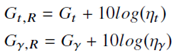
Real Gain
The real gain is a unitless performance value related to the peak radiation direction and efficiency of the antenna. This calculation assumes that the input gain for the calculated gain doesn't already account for efficiency.
|
(1) |
The real gain can be calculated in FreeFlyer using the following methods.
RFLink1.GetEffectiveReceiverGain(myEpoch); RFLink1.GetEffectiveTransmitterGain(myEpoch); |
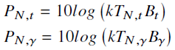
Noise Power
FreeFlyer determines noise power in dB based on the physical properties of the transmitter or receiver. In order to calculate the noise power, the noise temperature and bandwidth are assumed to be constant.
|
(2) |
The noise power can be calculated in FreeFlyer using the following methods.
RFLink1.GetReceiverNoise(); RFLink1.GetTransmitterNoise(); |
EIRP
The equivalent isotropically radiated power (EIRP) for the transmitter to the receiver is given in dB and references the transmitted power in W, the transmitter's line loss in dB, the transmitter's pointing loss in dB, and the real transmitter gain in dB.
|
(3) |
The EIRP can be calculated in FreeFlyer using the following method.
RFLink1.GetEIRP(myEpoch); |
Effective Antenna Area
The effective antenna area in square meters for the receiver is based on the real unitless receiver gain and the channel wavelength taken in meters. This calculation assumes that the antenna type is parabolic, and only finds the receiver area.
|
(4) |
The effective antenna area can be calculated in FreeFlyer using the following method.
RFLink1.GetEffectiveAntennaArea(myEpoch); |
Free Space Loss
Also known as the free space path loss (FSPL), this loss is associated with the link in free space in dB. The formula to arrive at this value is related to the transmitter wavelength and range between the receiver and transmitter both in meters.
|
(5) |
The FSPL can be calculated in FreeFlyer using the following method.
RFLink1.GetFreeSpaceLoss(myEpoch); |
Received/Transmitted Power
The power received and power transmitted calculations require the EIRP and link power margin in dB alongside the receiver's real gain inputs in dB and a number of losses in dB. The specific losses included in this formulation are the path loss, atmospheric loss, polarization loss, receiver pointing loss, and receiver line loss.
|
(6) |
The power can be calculated in FreeFlyer using the following methods.
RFLink1.ComputeReceivedPower(myEpoch); RFLink1.ComputeTransmittedPower(myEpoch); |
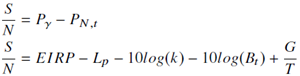
SNR
The signal-to-noise ratio (SNR) is also sometimes called the carrier-to-noise ratio (C/N or CNR). This ratio in dB is associated with the level of the signal power received in dB to the noise power transmitted in dB. The calculation itself uses received power and transmitter noise power inputs. There is an alternative calculation method that uses the receiver gain-to-noise temperature ratio (G/T) in dB/K as an input, EIRP in dB, transmitter bandwidth in MHz, and path loss in dB.
|
(7) |
The SNR can be calculated in FreeFlyer using the following methods. Using "Calculated" as the second argument finds the value by way of computing received power first. "FromReceiver" as the second argument finds the value based on user-defined power requirements. The numeric second argument is used when you want to specify the G/T received as noted in the alternative calculation method above.
RFLink1.GetSignalToNoiseRatio(myEpoch, "Calculated"); RFLink1.GetSignalToNoiseRatio(myEpoch, "FromReceiver"); RFLink1.GetSignalToNoiseRatio(myEpoch, 100); |
Energy per Bit to Noise Power Spectral Density Ratio
The energy per bit to noise power spectral density ratio, frequently abbreviated to Eb/No, is in units of dB. To calculate this value, FreeFlyer uses the SNR in dB, the transmitter bandwidth in MHz, and the symbol rate found from the bit rate input and modulation type.
|
(8) |
The Eb/No can be calculated in FreeFlyer using the following method.
RFLink1.GetEnergyPerBitToNoisePowerSpectralDensityRatio(myEpoch, "FromReceiver"); |
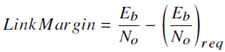
Link Margin
The link margin in dB can be found in a number of ways much like the SNR above. You must input either the defined SNR requirement, the Eb/No requirement, or the bit error rate (BER) requirement in order to develop the first Eb/No value used in the following formula to calculate the link margin.
|
(9) |
The link margin can be calculated in FreeFlyer using the following approaches.
// Compute the link margin by achieving a desired SNR at an epoch RFLink1.ComputeLinkMargin(myEpoch, "Calculated", 0 /* Carrier SNR */, 2 /* Achieve SNR of 2dB */);
// OR...
// Compute the link margin by back-solving using the receiver's SNR Variable receiverSNR = RFLink1.GetSignalToNoiseRatio(myEpoch, "Calculated"); // Get the receiver SNR RFLink1.ComputeLinkMargin(myEpoch, "FromReceiver", 0, receiverSNR);
// OR...
// Compute the link margin by using the BER Variable desiredBER = 20; // Some value in MHz RFLink1.ComputeLinkMargin(myEpoch, 100 /* G/T */, 2 /* Use BER */, desiredBER); |
Example: Determining Required Transmitter Power or Received Power
In this example, the required power to transmit an RF signal and the received RF signal power are reported.
|
Example: Determine the Effective Gain and Visualize the Gain Pattern Using GraphicsOverlay
An RFLink object is created in this example between a GroundStation and a Spacecraft to determine the effective gain for both the transmitter and receiver. The antenna file is then loaded into a GraphicsOverlay to help visualize the antenna gain pattern, specifically the difference in gain values surrounding the Spacecraft.
|
See Also
•RFLink Properties and Methods