By default, FreeFlyer uses a spherical method to calculate Solar Radiation Pressure (SRP). Users can perform higher fidelity SRP modeling through the use of a flat plate model that represents the geometry of your Spacecraft. Users can define the size and orientation of plates with respect to the Spacecraft Body Coordinate System, configure their plates to track the Sun in either single-axis or two-axis rotation, and query the SRP force and torque generated by the PlateModel. Once the PlateModel is defined, users can visualize their flat plate model in Mission Views to visually confirm the plate configuration, including the plates' size, location, and normal direction. After the plate model is configured properly, users can easily export the PlateModel configuration to import into any other FreeFlyer Mission Plan.
The following Sample Mission Plans (included with your FreeFlyer installation) demonstrate the use of the PlateModel object:
|
Flat Plate Box with Four Wings Sample Mission Plan
This page is divided into the following sections:
Background
The flat plate model approximates the shape of a satellite by a collection of flat plates, each of them having different reflectivity properties representing different sides of the satellite. In this approach the magnitude of the SRP acceleration will vary depending on the satellite's orientation with respect to the Sun.(1) The formula used to calculate the force for each plate(2) is:
|
(1) |

Where:
•PSR ≡ Solar Radiation Pressure •Aplate ≡ Area of flat plate •CRdiffuse ≡ Coefficient of Diffuse Reflectivity of the Plate •CRspecular ≡ Coefficient of Specular Reflectivity of the Plate •cosθ ≡ The angle between the Sun vector and the normal of the plate •N ≡ Normal of the plate •U ≡ Unit vector from the Spacecraft to the Sun •scb ≡ Shadowing coefficient for the Spacecraft's Central Body |
The Solar Radiation Pressure (PSR) from Equation 1 is calculated using the formula in Equation 2:
|
(2) |
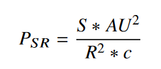
Where:
•S ≡ Mean solar flux at one astronomical unit (AU), defined as 1,358.0 W/m2(3) •AU ≡ Astronomical Unit (the distance from the Earth to the Sun), defined as 149,597,870.0 km •R ≡ Distance from the Spacecraft to the Sun •c ≡ Speed of light, defined as 299,792.458 km/s |
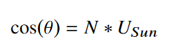
The angle between the Sun vector and the normal of the plate (cosθ) is calculated using Equation 3:
|
(3) |
Where:
•N ≡ Normal of the plate •U ≡ Unit vector from the Spacecraft to the Sun |
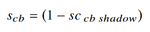
For most systems the shadowing coefficient (scb) is calculated using the formula in Equation 4, but for Earth/Moon systems the shadowing coefficient (scb) is calculated using the formula in Equation 5.
|
(4) |
|
(5) |
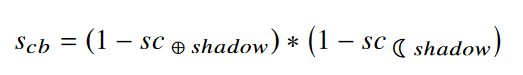
Where:
•sccb shadow ≡ Percent shadow of the Central Body |
Specular and diffuse reflectivity vary for different materials and can change over time with changing aspect toward the Sun. Specular reflectivity is the mirror-like reflection of light from a surface, where each incident ray is reflected at the same angle to the surface normal as the incident ray. Diffuse reflectivity is the reflection of light such that a ray incident on the surface is scattered. As an example, black paint may maintain a coefficient of specular reflectivity of 0 and diffuse reflectivity of ~0 over time; however, a material such as polished aluminum may start with a coefficient of specular reflectivity of 0.8 and diffuse reflectivity of ~0.1 but over time those values will decrease/increase accordingly.(4) It's important to configure each plate with realistic reflectivity values in order to get accurate force and torque results.
The PlateModel will automatically consider the Spacecraft's central body as the shadowing body. If the central body is the Earth or Moon, then both the Earth and Moon will be modeled as shadowing bodies. It is important to note, Plates do not cast shows on other plates; however, you can use the Plate.SRPAreaScaleFactor property to scale the force generated due to SRP on a plate to simulate "self shadowing" where one plate generates less force because it is behind another Plate.
Plates are one-sided, meaning that they only generate SRP when sunlight hits the ActiveFace, and it is transparent to SRP from the other side (the non-active face generates zero SRP). The nominally active face is determined by the order that the vertices are specified. This right-hand rule is applied to the first three vertices to determine the normal direction for the plate. You can reverse the normal direction and change the active face for the plate by setting the Plate.ActiveFace property to 1 or by changing the order that the vertices are specified.
References:
1."Using Spherical Harmonics to Model Solar Radiation Pressure Accelerations," Farrés, A., Folta D. and Webster C., AAS/AIAA Astrodynamics Specialist Conference, 2017 2.Vallado, D.A.: Fundamentals of Astrodynamics and Applications, 3rd edn. Microcosm Press, Hawthorne and Springer, New York (2007) 3.Equation 3-59, Page 76 of Wertz, James R., Spacecraft Attitude Determination and Control, Kluwer Academic Publishers, Boston, MA 4."Modelling of solar radiation pressure effects: Parameter analysis for the Microscope Mission," List, M., Bremer, S., Rievers, B., & Selig, H., International Journal of Aerospace Engineering, 2015 |
Enabling Flat Plate Modeling
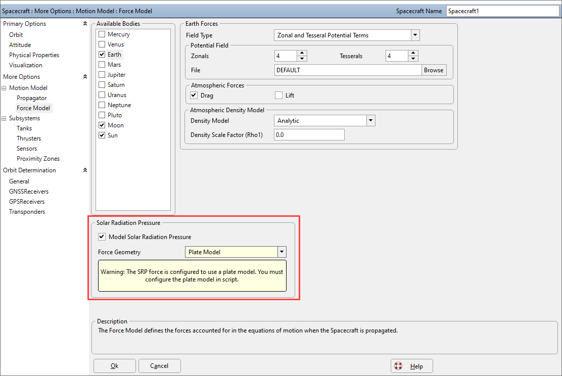
To enable SRP forces, edit the Spacecraft object, proceed to the Force Model page, and check the "Solar Radiation Pressure" check box, as shown below. Once SRP forces are enabled, ensure that the PlateModel is selected in the Force Geometry drop-down menu.
To enable Flat Plate Solar Radiation Pressure via FreeFlyer script, use the syntax shown below:
Spacecraft sc;
(sc.Propagator AsType Integrator).ForceModel.SRP = 1; (sc.Propagator AsType Integrator).ForceModel.SRPForceGeometry = 1; // 0 = Spherical // 1 = Flat Plate |
Defining a Plate with FreeFlyer Script
Adding Plates
The Spacecraft.PlateModel object holds all the settings for the plate model and contains a list of Plates called Spacecraft.PlateModel.Plates[]. Users have the ability to add Plates or a box of Plates to the PlateModel using one line of FreeFlyer script. The PlateModel.AddPlate() method has a number different overloads spanning from simply adding a Plate with a name to configuring a two-axis Sun tracking Plate all in one line of script. For more information on Single-Axis and Two-Axis Sun Tracking, refer to the Articulation section below. The script example below demonstrates adding a Plate to a PlateModel using the PlateModel.AddPlate() method:
// Add a new Plate, 'plate1', to the PlateModel sc.PlateModel.AddPlate("plate1");
// Define the Specular and Diffuse Reflectivity of the Plate sc.PlateModel.Plates[0].DiffuseReflectivity = 0.4; sc.PlateModel.Plates[0].SpecularReflectivity = 0.4; |
Configuring Rectangular and Circular Plates
Once a Plate has been added to the PlateModel, the Plate can be easily be configured with a rectangular or circular shape using the Plate.ConfigureRectangularShape() and Plate.ConfigureCircularShape() methods. These methods are convenient to easily model hardware attached to a Spacecraft such as a solar array or dish. The script examples below demonstrate how to configure a rectangular or circular shaped Plate to add to a PlateModel:
// Plate properties Variable wingLength = 5; // 5 meters Variable wingWidth = 7; // 7 meters Array yHat = {0, 1, 0}; // +Y direction for first direction in BCS defining rectangle dimension Array zHat = {0, 0, 1}; // +Z direction for second direction in BCS defining rectangle dimension Array centerPosition = {0, 0, 0}; // Center of BCS
// Add a Rectangular Plate sc.PlateModel.AddPlate("wing1"); sc.PlateModel.Plates[0].ConfigureRectangularShape(yHat, wingLength, zHat, wingWidth, centerPosition); |
Output:
Rectangular Plate Example
// Add Circular Plate Variable radius = 5; // 5 meters Variable numElements = 10; // The number of triangles used to approximate the circular shape
plate.ConfigureCircularShape(radius, numElements, centerPosition, {1,0,0}); |
Output:
Circular Plate Example
Creating Boxes of Plates
A user also has the ability to add a box of Plates to a Plate model using the PlateModel.AddBoxOfPlates() method. Using the PlateModel.AddBoxOfPlates() adds six Plates to the Spacecraft in a cube or rectangular prism shape. The box is defined by X, Y, and Z dimensions in the Spacecraft BCS and is centered at a user defined centerPosition. The syntax example below demonstrates how to configure a box of plates:
// Configure dimensions and origin Array dimensions = {2, 2, 1}; // 2m X, 2m Y, 1m Z Array centerPosition = {0,0,0}; // Center of Spacecraft BCS
// Add a box of Plates to the PlateModel sc.PlateModel.AddBoxOfPlates("bus", dimensions, centerPosition); sc.PlateModel.SetFaceColors(ColorTools.Cyan); // Set the face color to Cyan if the face is visible to the Sun sc.PlateModel.SetWireframeColors(ColorTools.Red); // Set the wireframe to be Red |
Output:
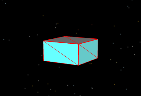
Box of Plates Example
Configuring Arbitrarily Shaped Plates
For shapes other than rectangles, circles, and boxes, you can manually assign the locations of the vertices to define the shape of the Plate with the Spacecraft.PlateModel.Plates[].Vertices property. The plate is defined using a triangle strip, where every three vertices defines a triangle and the plates' normal direction is defined using the right hand rule. Note, the vertices for a given plate must be coplanar. In the image below, a visual representation of the triangle strip winding rules used to define plates with vertices can be seen.
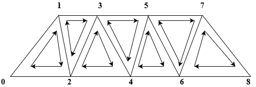
Triangle Strip Winding Rules
In the simple example below, a Plate with a specular reflectivity and diffuse reflectivity value of 0.4, is configured to have 3 vertices and a face color of yellow.
Alias plate = sc.PlateModel.Plates[0];
// Configure using AddPlate() method sc.PlateModel.AddPlate("plate", 0.4, 0.4); // Cr_Specular and Cr_Diffuse = 0.4
// Configure using vertices plate.NumberOfVertices = 3; plate.Vertices = [0, 0, 0; // First point - center of BCS 0, 1, 0; // Second point - 1 meter in the +Y direction 1, 0, 0]; // Third point - 1 meter in the +X direction
plate.FaceColor = ColorTools.Yellow; sc.PlateModel.VisualScale = 100000; // Increase the visual scale for visualization vw.Update(); |
Output:
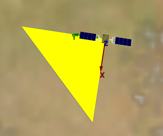
Simple Plate Example
Specifying Reflectivity Coefficients
For each Plate associated with the PlateModel users also have the ability to set the Diffuse Reflectivity, Specular Reflectivity, and SRP Area Scale Factor. As mentioned in the Background section, the diffuse reflectivity coefficient is the reflection of light such that a ray incident on the surface is scattered. Diffuse reflectivity is the ratio of the power of the reflected wave to that of the incident wave, where increasing the coefficient corresponds to a greater degree of scatter, thus decreasing power of the reflected wave.
Whereas, the specular reflectivity coefficient represents the mirror-like reflection of light from a surface, where each incident ray is reflected at the same angle to the surface normal as the incident ray. Specular reflectivity is the ratio of the power of the reflected wave to that of the incident wave, where increasing the coefficient corresponds to increasing power of the reflected wave.
Note: The sum of Spacecraft.PlateModel.Plates[].DiffuseReflectivity and Spacecraft.PlateModel.Plates[].SpecularReflectivity must be less than or equal to 1.
Querying Plate Attributes
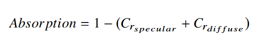
Along with defining parameters for a Plate, users can further analyze their Plates by reporting out the Absorption, Area, Center of Pressure, and Normals. A Plate's coefficient of absorption is computed as shown below:
The area of a plate is computed as the sum of each triangle in the triangle strip that defines the Plate's shape. For the area of a PlateModel projected along a particular direction, see the Querying PlateModel Force, Torque, and Area section below. The Spacecraft.PlateModel.Plates[].Normal property returns the normal vector for the Plate in the Spacecraft Body Coordinate System frame.
In the script example below, a Plate is configured using three vertices then the specular and diffuse reflectivity values are defined. Once the Plate is configured, the Plate's Area, Normal, Center of Pressure, and Absorption are reported.
// Configure using AddPlate() method sc.PlateModel.AddPlate("plate");
// Define the Specular and Diffuse Reflectivity of the Plate plate.DiffuseReflectivity = 0.4; plate.SpecularReflectivity = 0.4;
// Configure using vertices plate.NumberOfVertices = 3; plate.Vertices = [0, 0, 0; 0, 1, 0; 1, 0, 0];
Report plate.Area, plate.Normal, plate.CenterOfPressure, plate.Absorption; // Read-Only |
Output:
![]()
Note: Plates are one-sided, meaning it only generates SRP when sunlight hits the ActiveFace, and it is transparent to SRP from the other side (the non-active face generates zero SRP).
Simulating Self-Shadowing
The SRP Area Scale Factor scales the force generated due to SRP on the Plate and can be specified by the user to simulate "self-shadowing" where one plate generates less force because it is behind another Plate. The simple example below sets up two rectangular plates, one in front of the other, then assigns the "hidden" Plate to have a lower SRPAreaScaleFactor such that it will produce a lower force due to SRP because it is behind another Plate.
// Create the first rectangular plate sc.PlateModel.AddPlate("Front"); sc.PlateModel.Plates[0].ConfigureRectangularShape({0,1,0},5,{0,0,1},7,{0,0,3.5});
// Create the second rectangular plate (this plate will be behind the first plate) sc.PlateModel.AddPlate("Back"); sc.PlateModel.Plates[1].ConfigureRectangularShape({0,1,0},5,{0,0,1},7,{-1,0,0}); // The center position lies behind the first plates'
// Lower the SRPAreaScaleFactor because this Plate is behind the first plate sc.PlateModel.Plates[1].SRPAreaScaleFactor = 0.5;
While (sc.ElapsedTime < TimeSpan.FromDays(1)); // Only Report when the Spacecraft is in sunlight If (sc.InShadow() != 1); Report sc.ElapsedTime, sc.PlateModel.Plates[0].GetSRPForce(0), sc.PlateModel.Plates[1].GetSRPForce(0); End;
View sc; Step sc; End; |
Outputs:
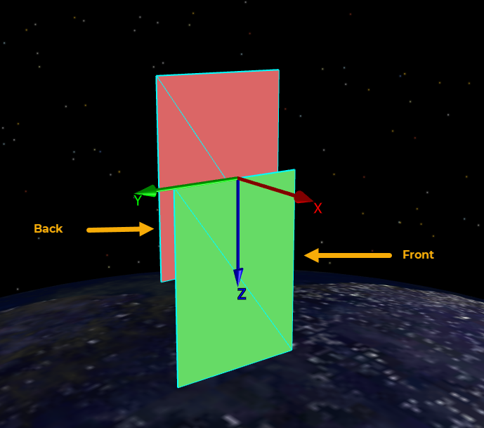
Model SRP Area Scale Factor with one Plate in front of another
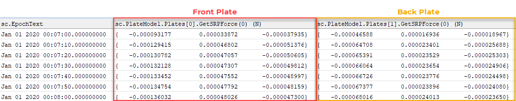
SRP Force for two Plates
As shown in the example above, the "Back" Plate lies behind the "Front" Plate so it will generate less SRP Force. By changing the SRPAreaScaleFactor value we have simulated that the "Back" Plate will generate half the SRP force that the "Front" Plate will generate and the results show that to be true.
Removing Plates
A user also has the ability to remove individual Plates or all Plates from a PlateModel using either the PlateModel.RemovePlate() method or PlateModel.RemoveAllPlates() method as shown below:
// Remove a single Plate by name sc.PlateModel.RemovePlate(“plateName”);
// Remove a single Plate by it's index value sc.PlateModel.RemovePlate(index);
// Remove all Plates from the PlateModel sc.PlateModel.RemoveAllPlates(); |
Articulation
Users can define the orientation of Plates with respect to the Sun by configuring their Plates to track the Sun in either single-axis or two-axis rotation by using the Spacecraft.PlateModel.Plates[].ArticulationModel property.
Setting the Plate.ArticulationModel property equal to zero corresponds to a Plate which does not track the Sun.
Single Axis Articulation
Setting the Plate.ArticulationModel equal to one corresponds to a Plate which will rotate about its primary axis to the Sun. The Spacecraft.PlateModel.Plates[].PrimaryRotationAxis property is used to define a vector describing the direction of the Plate's primary rotation axis, specified in the Spacecraft Body Coordinate System. The position of the pivot point of the Plate's primary rotation axis in the Spacecraft's BCS can be defined using the Spacecraft.PlateModel.Plates[].PrimaryPivotPoint property.
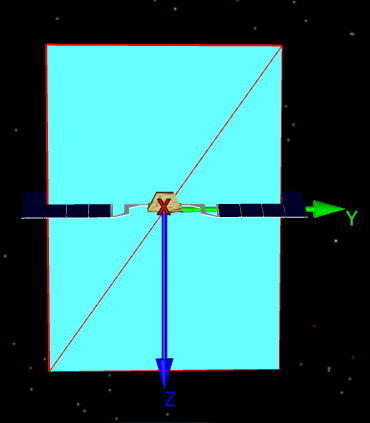
For a better understanding, a visual representation of a single-axis Sun tracking articulation model can be seen below. In the following two examples, a box of plates is used to model the Spacecraft's "bus" and a rectangular plate is used to model single-axis and two-axis articulation. For the single-axis tracking example, once the Plates are configured, the rectangular plate is set to use a single-axis tracking model with a primary rotation axis on the +Y axis, and a primary pivot point at the center of the Spacecraft's BCS. For visualizations, the PrimaryRotationAxis can be seen in red along the Y-axis of the Spacecraft's BCS. The normal of the rectangular plate can be seen in aqua tracking the Sun using only one degree of freedom.
// Single-Axis Sun-Tracking sc.PlateModel.Plates[0].ArticulationModel = 1; sc.PlateModel.Plates[0].PrimaryRotationAxis = {0.0, 1.0, 0.0}; // Primary Rotation Axis +Y sc.PlateModel.Plates[0].PrimaryPivotPoint = {0.0, 0.0, 0.0}; // Primary Pivot Point center of BCS
// Visualization sc.PlateModel.Plates[0].NormalLength = 10; sc.PlateModel.Plates[0].NormalColor = ColorTools.Aqua; sc.PlateModel.Plates[0].PrimaryRotationAxisLength = 5; sc.PlateModel.Plates[0].PrimaryRotationAxisColor = ColorTools.Red;
sc.PlateModel.DrawNormals = 1; // Draw Normals sc.PlateModel.DrawRotationAxes = 1; // Draw Rotation Axis |
Output:

Single-Axis Sun Tracking Articulation Model
Perfect Tracking with Two Axis Articulation
Setting the Plate.ArticulationModel property equal to two corresponds to a plate which will rotate about its primary and secondary axes to track the Sun. When using two-axis Sun tracking as the articulation model, the secondary rotation axis intercept must be specified. The Plates[].SecondaryRotationAxisIntercept property specifies the location where the second rotation axis intersects the primary rotation axis and is measured (in meters) from the primary pivot point along the primary rotation axis.
For a better understanding, a visual representation of a two-axis Sun tracking articulation model can be seen below.
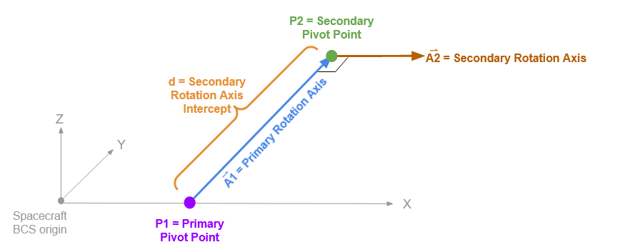
Perfect Tracking Diagram
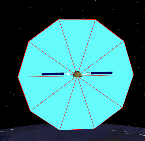
For the two-axis tracking example, once the Plates are configured, the rectangular plate is set to use a two-axis tracking model with a primary rotation axis on the +Y axis, and a primary pivot point at the center of the Spacecraft's BCS. In addition, the SecondaryRotationAxisIntercept is set to 2, meaning that the intercept will be two meters from the primary pivot point along the primary rotation axis (+Y direction). For visualizations, the PrimaryRotationAxis can be seen in red along the Y-axis of the Spacecraft's BCS and the SecondaryRotationAxis is colored lime.The normal of the rectangular plate can be seen in aqua and is collinear with the Sun vector as the Plate is pointing straight at the Sun.
// Two-Axis Sun-Tracking sc.PlateModel.Plates[0].ArticulationModel = 2; sc.PlateModel.Plates[0].PrimaryRotationAxis = {0.0, 1.0, 0.0}; // Primary Rotation Axis +Y sc.PlateModel.Plates[0].PrimaryPivotPoint = {0.0, 0.0, 0.0}; // Primary Pivot Point center of BCS sc.PlateModel.Plates[0].SecondaryRotationAxisIntercept = 2; // 2 meters from primary pivot point along the primary rotation axis
// Visualization sc.PlateModel.Plates[0].NormalLength = 10; sc.PlateModel.Plates[0].NormalColor = ColorTools.Aqua; sc.PlateModel.Plates[0].PrimaryRotationAxisLength = 5; sc.PlateModel.Plates[0].PrimaryRotationAxisColor = ColorTools.Red; sc.PlateModel.Plates[6].SecondaryRotationAxisLength = 7; sc.PlateModel.Plates[6].SecondaryRotationAxisColor = ColorTools.Lime;
sc.PlateModel.DrawNormals = 1; // Draw Normals sc.PlateModel.DrawRotationAxes = 1; // Draw Rotation Axis
|
Output:
Two-Axis Sun Tracking Articulation Model
Getting Updated Geometry for Articulating Plates
While propagating, to get the updated normal vector for a Plate as it rotates to track the Sun, use the Spacecraft.PlateModel.Plates[].GetUpdatedNormal() method. The Spacecraft.PlateModelPlates[].GetUpdatedVertices() method can be used to get the vertex locations in the Spacecraft's BCS as the plate points to track the Sun. Similarly, the Spacecraft.PlateModel.Plates[].GetUpdatedCenterOfPressure() method returns the updated center of pressure for a specified plate as the plate points to track the Sun.
While (sc.ElapsedTime < TimeSpan.FromHours(12));
Report sc.EpochText, sc.PlateModel.Plates[0].GetUpdatedCenterOfPressure(); Report sc.EpochText, sc.PlateModel.Plates[0].GetUpdatedVertices(); Report sc.EpochText, sc.PlateModel.Plates[0].GetUpdatedNormal();
Step sc; Update vw; End; |
Querying PlateModel Force, Torque, and Area
Query Values
A user can query values such as the SRP force, torque, or incident area throughout the duration of the Spacecraft's propagation. The PlateModel.GetSRPForce() method returns the current SRP force on the PlateModel and can be reported in either a body frame (Spacecraft BCS) or in an inertial frame (ICRF).
The PlateModel.GetSRPTorque() method returns the current SRP torque on the PlateModel about the Spacecraft's center of mass (COM) or from a user specified reference point in the Spacecraft BCS.
The PlateModel.GetIncidentArea() method returns the incident area of the PlateModel as seen from a specified direction. The direction can be specified in either the Spacecraft BCS fixed frame or ICRF inertial frame. The script example shown below demonstrates how to query these values once a PlateModel has been configured:
Variable frame = 0; // Body Array arrayReferencePoint = {0,0,0}; // Center of BCS Array direction = {1, 1, 1}; // Specified in BCS
// Arrays for plots Array srpForce[3]; Array srpTorque[3];
While (sc.ElapsedTime < TimeSpan.FromHours(12));
srpForce = sc.PlateModel.GetSRPForce(0)*1e6; // Force in the SC body frame srpTorque = sc.PlateModel.GetSRPTorque()*1e6; // Torque in the SC body frame
// Plots Plot sc.ElapsedTime, srpForce[0], srpForce[1], srpForce[2]; Plot sc.ElapsedTime, srpTorque[0], srpTorque[1], srpTorque[2];
Report sc.PlateModel.GetIncidentArea(frame, direction); // incident direction is specified in the SC BCS frame // flattens the geometry in that direction
Step sc; End; |
Outputs:
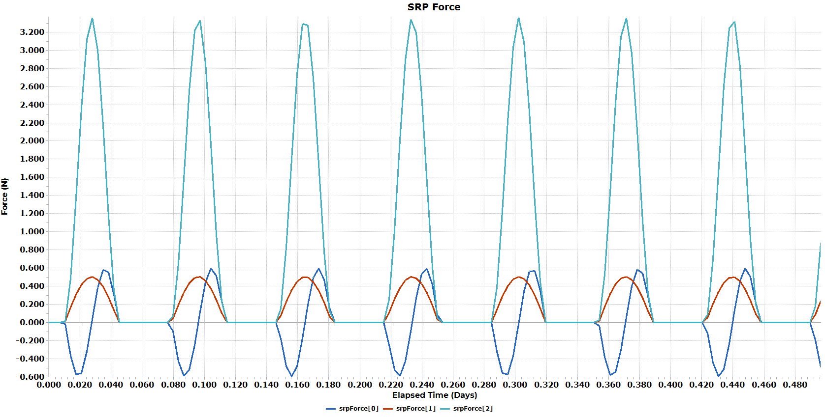
SRP Force Plot
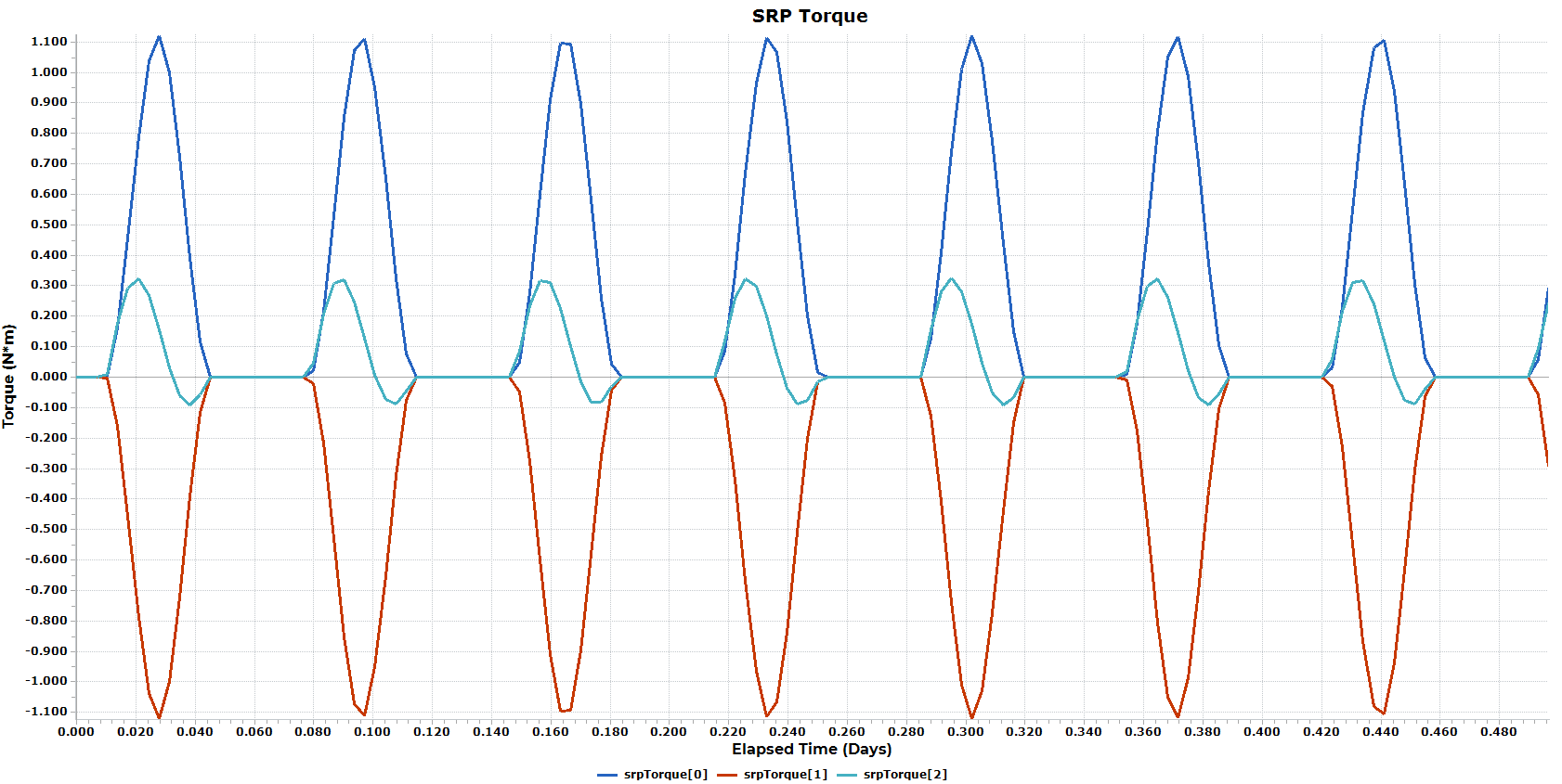
SRP Torque Plot
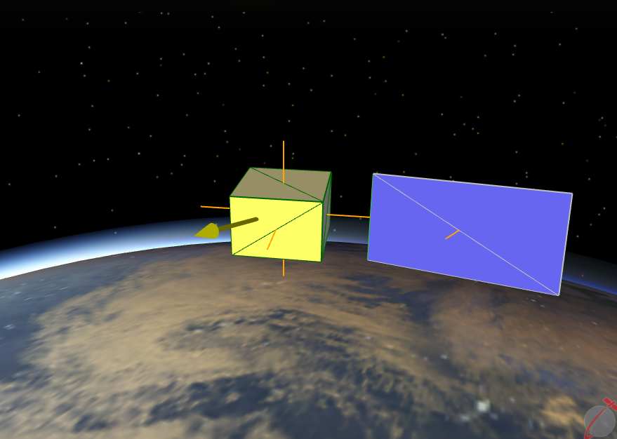
Visualizing Plates
Once the PlateModel is defined, users can visualize their flat plate model in Mission Views to visually confirm the plate configuration, including the plates' size, location, and normal direction. Users have the ability visualize a PlateModel using the Spacecraft.PlateModel.Visible property and can increase or decrease the scale of the PlateModel using the Spacecraft.PlateModel.VisualScale property. Users can set the colors for individual Plates using the Plate.FaceColor property or for the whole PlateModel at once using the PlateModel.SetFaceColors() method. Users can choose to draw the PlateModel as a solid, wireframe, or solid with wireframe using the Spacecraft.PlateModel.DrawMethod property. As an example, the script snippet below demonstrates how to create a box of plates and draw the PlateModel with different colors for the faces and wireframe.
// Add the main "bus" of the satellite Array dimensions = {1, 1, 0.7}; // 1m X, 1m Y, 0.7m Z Array centerPosition = {0,0,0}; // Center of Spacecraft BCS sc.PlateModel.AddBoxOfPlates("bus", dimensions, centerPosition); sc.PlateModel.SetFaceColors(ColorTools.Gold); // Set all face colors to Gold sc.PlateModel.SetWireframeColors(ColorTools.DarkGreen); // Set the wireframe to be DarkGreen sc.PlateModel.DrawMethod = 2; // Draw both solid faces and a wireframe |
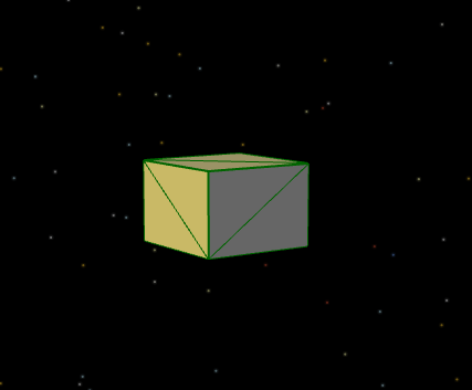
Box of Plates drawn with solid faces and a wireframe
Note: In the example above, the faces will be colored gold when they are in view of the Sun.
The Spacecraft.PlateModel.DrawNormals property can be used to determine whether Plate normals should be drawn in views.
sc.PlateModel.DrawNormals = 1; |
Draw Normals for all Plates
If a Plate is defined with either a single-axis or two-axis sun tracking articulation model, the user can visualize the rotation axes using the Spacecraft.PlateModel.DrawRotationAxes property.
// Two-Axis Sun-Tracking sc.PlateModel.Plates[0].ArticulationModel = 1; sc.PlateModel.Plates[0].PrimaryPivotPoint = {0,1,0}; sc.PlateModel.Plates[0].PrimaryRotationAxis = {0,1,0}; sc.PlateModel.Plates[0].SecondaryRotationAxisIntercept = 0;
// Visuals sc.PlateModel.Plates[0].PrimaryRotationAxisLength = 2; sc.PlateModel.Plates[0].SecondaryRotationAxisLength = 1; sc.PlateModel.Plates[0].FaceColor = ColorTools.DarkBlue; sc.PlateModel.Plates[0].WireframeColor = ColorTools.Silver;
sc.PlateModel.DrawNormals = 1; sc.PlateModel.DrawRotationAxes = 1; sc.PlateModel.SetNormalLengths(0.5); |
Draw Rotation Axis for Articulating Plate
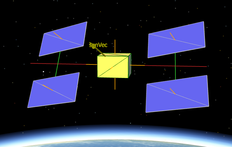
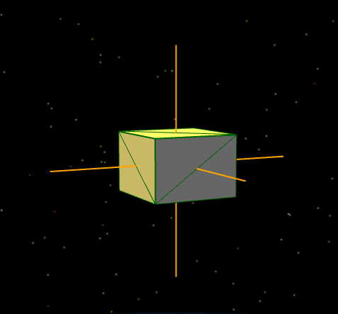
In the example below, the PlateModel is drawn as a solid by setting the Spacecraft.PlateModel.DrawMethod property equal to 0 and the faces will be yellow. The normals are drawn by setting the Spacecraft.DrawNormals property equal to 1 and the normals are colored orange using the PlateModel.SetNormalColors() method. Finally, the PlateModel is set to be visualized in the view by setting the Spacecraft.PlateModel.Visible property equal to 1 and the visual scale is decreased by setting the Spacecraft.PlateModel.VisualScale property equal to 1000 meters.
sc.PlateModel.DrawMethod = 0; // 0 = solid, 1 = wireframe sc.PlateModel.SetFaceColors(ColorTools.Yellow); // set whole model face color
sc.PlateModel.DrawNormals = 1; sc.PlateModel.SetNormalColors(ColorTools.Orange); sc.PlateModel.SetNormalLengths(10); // 10 meters
// Ability to hide the PlateModel from the view sc.PlateModel.Visible = 1; // Visualize the PlateModel in the view
// Remove the PlateModel from the view vw.SetShowObject(sc.PlateModel.ObjectId, 0);
sc.PlateModel.VisualScale = 1000; // 1000 meters |
Note: For a plate in non-tracking mode, rotation axes can not be drawn. For a plate in single-axis mode, only the primary axis will be drawn. For a plate in two-axis mode, both the primary and secondary axes will be drawn.
Importing and Exporting PlateModel Configurations
Once the PlateModel is configured, the Put command can be used to store the PlateModel configuration in an external XML-formatted file to be used in any Mission Plan. Similarly, the Get command can be used to retrieve a saved PlateModel that has been stored in an external file. To save a PlateModel to an external file, or retrieve a PlateModel from a previously saved configuration, use the syntax shown below:
// Save to file Put sc.PlateModel to “plateModel1.FFObjectFile”;
// Get a stored configuration from file Get sc.PlateModel from “plateModel1.FFObjectFile”; |
See Also
•ForceModel Properties and Methods