You can use FreeFlyer to create simulated observation data for any of the observation types shown in the table below. The first step is to create an instance of the desired Observation object. For example:
BRTSObservation BRTSObservation1; CustomObservation CustomObservation1; GNSSObservation GNSSObservation1; GroundStationObservation GroundStationObservation1; PointSolutionObservation PointSolutionObservation1; SpacecraftObservation SpacecraftObservation1; TDRSObservation TDRSObservation1; |
This page is covers the following topics:
1.Set Source and Target - configure the observing and observed objects in any observation 2.Set Measurement Types and Corrections 3.Simulating 3-way Observations |
Set Source and Target
Once the observation object has been created, you will need to set the observing object, and observed object. The object being observed will be the target Spacecraft, or in the case of GNSS pseudorange observations, the GNSS receiver attached to the target Spacecraft. The observing object will vary based on the type of observation, as shown in the table below.
If a Transponder is specified as the object being observed, this models a transponder delay on the Spacecraft. If a Sensor is specified in addition to a GNSS Receiver, Transponder, or TDRS Transponder, the Sensor's X, Y, and Z position properties will be used to model an offset from the origin of the Spacecraft body coordinate system (BCS) when modeling measurements.
Observation Type |
Object Being Observed |
Observing Object |
Relay |
TDRS Transponder OR TDRS Transponder and Sensor |
Ground Antenna |
Ground Antenna (Remote Ground Terminal) |
|
User-Specified |
User-Specified |
User-Specified |
|
Spacecraft OR Transponder OR Transponder and Sensor |
Ground Antenna |
N/A |
|
Spacecraft |
GNSS Receiver OR GNSS Receiver and Sensor |
N/A |
|
GNSS Receiver OR GNSS Receiver and Sensor |
Spacecraft |
N/A |
|
Spacecraft OR Transponder OR Transponder and Sensor |
Sensor |
N/A |
|
Spacecraft OR Transponder OR Transponder and Sensor |
Ground Antenna |
TDRS Transponder OR TDRS Transponder and Sensor |
Note: DSN Observations are derived from Ground Station Observations and are compatible with DSN 60-Byte Observation files and TRK-2-34 files, but cannot be simulated.
In order to set the observation target and source in script, the SetObjectBeingObserved and SetObserver methods are used. The syntax example below demonstrates how these methods are used in the case of a Ground Station observation.
// Set observer GroundStationObservation1.SetObserver(GroundStation1.Antenna);
// Set object being observed GroundStationObservation1.SetObjectBeingObserved(Spacecraft1);
// --OR-- GroundStationObservation1.SetObjectBeingObserved(Spacecraft1.Transponders[0]);
// --OR-- Spacecraft1.Transponders[0].Attach(Spacecraft1.Sensors[0]); GroundStationObservation1.SetObjectBeingObserved(Spacecraft1.Transponders[0], Spacecraft1.Sensors[0]); |
For spacecraft-to-spacecraft observations, similar syntax can be used to set the observation target and source. The SpacecraftObservation object can store the observing Spacecraft's position at the time of observation through the ObserverPosition property.
// Set Observer SpacecraftObservation1.SetObserver(Spacecraft1.Sensors[0]);
// Set the SpacecraftObservation object to hold the position of the // observing Spacecraft. The UseObserverPosition property of the // SpacecraftObservation object cannot be set to True when both // UseRange/RangeRate and UseLightTimeCorrection are used. // See the Spacecraft Observations entry in the table under the // 'Set Measurement Types and Corrections' section for more information. SpacecraftObservation1.UseObserverPosition = 1;
// --OR-- SpacecraftObservation1.SetObjectBeingObserved(Spacecraft2);
// --OR-- SpacecraftObservation1.SetObjectBeingObserved(Spacecraft2.Transponders[0]);
// --OR-- Spacecraft2.Transponders[0].Attach(Spacecraft2.Sensors[0]); SpacecraftObservation1.SetObjectBeingObserved(Spacecraft2.Transponders[0], Spacecraft2.Sensors[0]);
// Retrieve observing Spacecraft position at the time of observation Report SpacecraftObservation1.ObserverPosition; |
Set Measurement Types and Corrections
The next step is to set a series of flags, indicating what measurement types should be included in the simulated observation. You can also set flags that specify whether or not to apply certain corrections to the observation. The available measurement types and other options vary for each observation type:
Observation Type |
Measurement Types |
Other Options |
BRTS observations |
Two-Way Doppler Two-Way Range |
Ionospheric Correction Light Time Correction Tropospheric Correction |
Custom observations |
User-Specified |
User-Specified |
Ground Station observations |
Range Range Rate Azimuth Elevation Right Ascension Declination |
Ionospheric Correction Light Time Correction Tropospheric Correction |
Point Solution observations |
X Y Z VX VY VZ |
None |
GNSS observations |
Ionospheric Correction Light Time Correction (always on) |
|
Spacecraft observations [1] |
Range Range Rate Azimuth Elevation Right Ascension Declination |
Ionospheric Correction Observer Position Light Time Correction |
TDRS observations |
One-Way Doppler Two-Way Doppler Two-Way Range |
Ionospheric Correction Light Time Correction Tropospheric Correction |
[1] Note: The UseObserverPosition property of the SpacecraftObservation object cannot be set to True when both UseRange/RangeRate and UseLightTimeCorrection are used. When observations are processed in any of the FreeFlyer estimators and UseObserverPostion is set to True, the data in the ObserverPosition array is copied into the Observing Spacecraft's state and there is no propagation. The state of the Observing spacecraft is at the observation epoch, and the ObserverPosition with a velocity of zero. Processing Range/RangeRate data along with light time corrections enabled require backwards propagation of the observer, which cannot be done with only position data. Light time corrections can be enabled for the Right Ascension/Declination or Azimuth/Elevation measurements.
The example below shows how to set the flags relevant to a Ground Station observation via FreeFlyer script:
GroundStationObservation1.UseRange = 1; GroundStationObservation1.UseRangeRate = 1; GroundStationObservation1.UseAzimuth = 1; GroundStationObservation1.UseElevation = 1; GroundStationObservation1.UseRightAscension = 0; GroundstationObservation1.UseDeclination = 0;
GroundStationObservation1.UseIonosphericCorrection = 1; GroundStationObservation1.UseLightTimeCorrection = 1; GroundStationObservation1.UseTroposphericCorrection = 1; |
Note: The tropospheric correction calculation relies on the GroundStation.MonthlyRefractivity property, so it is possible to configure different values for the refractivity when simulating the measurements vs. when processing. Similarly, the ionospheric correction calculation relies on the FF_SolarSystem.IonosphereOptions.ScaleFactor property, which can be configured to scale the ionospheric correction values differently for simulating vs. processing.
Simulating 3-way Observations
The receiving and transmitting antennas for Ground Station Observations can be configured using the SetObserver(), SetTransmittingAntenna(), and SetReceivingAntenna() methods. When only SetObserver() is used, a single GroundStation is both the transmitter and receiver - this is sometimes called a "2-way" observation. The SetTransmittingAntenna() and SetReceivingAntenna() methods can be used to specify two different GroundAntennas as the transmitter and receiver - this is sometimes called a "3-way" observation. In 2-way observations, the ground antenna transmits a signal to the Spacecraft, which generates a phase coherent downlink signal that is transmitted back to the same ground antenna. In 3-way observations, the Spacecraft is tracked by two different GroundStations. The primary station transmits a signal to the Spacecraft, which returns a signal to both GroundStations, allowing the primary station to behave in 2-way mode while the received frequency at the secondary station can be used for comparison. In this way, the 3-way observation is formed at the second station and based off data from both stations, while the 2-way observation only uses data based off the primary station.
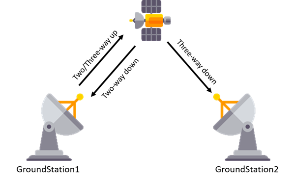
GroundStation1 alone forms a 2-way measurement, GroundStation2 as the receiver yields a 3-way measurement
This can be configured in script as follows:
// Two-way mode option 1 GroundStationObservation1.SetObserver(GroundStation1.Antenna);
// Two-way mode option 2 GroundStationObservation1.SetTransmittingAntenna(GroundStation1.Antenna); GroundStationObservation1.SetReceivingAntenna(GroundStation1.Antenna);
// Three-way mode GroundStationObservation1.SetTransmittingAntenna(GroundStation1.Antenna); GroundStationObservation1.SetReceivingAntenna(GroundStation2.Antenna); |
Set Measurement Biases and Noise
Next, the biases and noise for each measurement must be set. The measurement bias and noise are properties of the Observing object (except when working with the GNSSObservation, which uses the measurement bias and noise properties of the object being observed - the GNSSReceiver. See the table in "Set Source and Target", above). For instance, the Range Bias and Noise properties associated with a GroundStationObservation are associated with the GroundAntenna object.
The example below shows how to set the bias and noise properties for a Ground Station observation that has Canberra as the observing Ground Station:
// Set Ground Station bias and noise properties for Range measurements GroundStationObservation1.SetObserver(Canberra.Antenna);
Canberra.Antenna.OD.GroundObservation.Range.Bias.Value = 0.005; // 5 m bias Canberra.Antenna.OD.GroundObservation.Range.Noise = 0.003; // 3 m 1-sigma noise |
Also, since the GNSSReceiver object is associated with both PointSolution observations and GNSS pseudorange observations for Global Navigation Satellite System (GNSS) constellations, the bias and noise properties associated with each observation type are called out explicitly as appropriate. An example for PointSolution observations is shown below:
Alias receiver = EstimatedSC.GNSSReceivers[0]; // This alias is used to shorten the script examples below
// Set the GNSS Receiver bias and noise properties used with GNSS pseudorange observations GNSSObservation1.SetObjectBeingObserved(receiver);
receiver.OD.GNSSObservation.GPS.AddMeasurement('C1C', 0.001); // 1 m 1-sigma noise
// Set the GNSS Receiver bias and noise properties used with PointSolution observations PointSolutionObservation1.SetObserver(receiver);
receiver.OD.PointSolutionObservation.X.Bias.Value = 0.0; // no bias receiver.OD.PointSolutionObservation.Y.Bias.Value = 0.0; // no bias receiver.OD.PointSolutionObservation.Z.Bias.Value = 0.0; // no bias receiver.OD.PointSolutionObservation.VX.Bias.Value = 0.0; // no bias receiver.OD.PointSolutionObservation.VY.Bias.Value = 0.0; // no bias receiver.OD.PointSolutionObservation.VZ.Bias.Value = 0.0; // no bias
receiver.OD.PointSolutionObservation.X.Noise = 0.004; // 4 m 1-sigma noise receiver.OD.PointSolutionObservation.Y.Noise = 0.004; // 4 m 1-sigma noise receiver.OD.PointSolutionObservation.Z.Noise = 0.004; // 4 m 1-sigma noise receiver.OD.PointSolutionObservation.VX.Noise = 0.00001; // 1 cm/s 1-sigma noise receiver.OD.PointSolutionObservation.VY.Noise = 0.00001; // 1 cm/s 1-sigma noise receiver.OD.PointSolutionObservation.VZ.Noise = 0.00001; // 1 cm/s 1-sigma noise |
For GNSS pseudorange observations, a noise value must be specified when adding a measurement code to the model. The value can be changed by accessing properties of the Pseudoranges Array for the appropriate GNSS constellation. An example is shown below:
Alias receiver = EstimatedSC.GNSSReceivers[0]; // This alias is used to shorten the script examples below
// Set the GNSS Receiver bias and noise properties used with GNSS pseudorange observations GNSSObservation1.SetObjectBeingObserved(receiver);
receiver.OD.GNSSObservation.GPS.AddMeasurement('C1C', 0.001); // 1 m 1-sigma noise receiver.OD.GNSSObservation.GPS.Pseudoranges[0].Noise = 0.005; // 5 m 1-sigma noise |
Simulate Data
Now, your observation object is set up and ready to be populated with simulated data. This is done using the Spacecraft.SimulateTrackingData() method. The SimulateTrackingData method simulates orbit determination tracking data, which can then be written out to a file or included in an estimation process. The measurement noise, bias, and error model settings are determined by the Observation object (such as a GroundStationObservation) and its associated observing object (such as a GroundAntenna).
Spacecraft1.SimulateTrackingData(GroundStationObservation1); |
Simulating GNSS Pseudorange Data
Simulating observations from Global Navigation Satellite System (GNSS) constellations, such as GPS or Galileo, presents some unique considerations, including the number of simultaneous observations, highly variable visibility, and modeling the clocks aboard the observing constellations. This section details how these considerations can be handled within FreeFlyer.
First of all, since the number of spacecraft in the observing constellation that are visible can change significantly over time or based on your Spacecraft's orbit, a List of GNSSObservations is provided as an argument to the SimulateTrackingData method. The dimension of the List is the maximum number of GNSS Observations that can be simulated. If a fewer number of observing spacecraft are visible, the remaining elements of the List are left empty.
Secondly, since the visibility of observing spacecraft can change rapidly over time, the user is not required to set the Observer of each GNSSObservation in the List. This is done internally by FreeFlyer, so that the Observer is automatically set up as a Spacecraft in a GNSS constellation such as GPS or Galileo.
When simulating GNSS Observations the user has two primary options for defining the observing constellation. The user can define the constellation using a RinexNavFile or define the constellation in script.
1.When the constellation is being propagated using a RinexNavFile, the Clock Bias of each spacecraft is computed based on the Broadcast Ephemeris data contained in the RinexNavFile. Also, a nadir-pointing Sensor with a half-angle of 21.3 degrees is automatically attached to each spacecraft to determine visibility. A Formation object using a RinexNavFile can be configured through the Object Browser or in script, as shown below. Users can select whether the data in the RinexNavFile is representative of a specific GNSS constellation or a combination of constellations.
 Formation initialized with RinexNavFile
The example below demonstrates how to define a Formation with a RinexNavFile in script:
2.When the constellation is defined in script without a RinexNavFile, a GNSSReceiver and a nadir-pointing Sensor must be attached to each spacecraft in the Formation. The Clock Bias of the receiver will be used to determine the Clock Bias for each spacecraft, and the Sensor will be used to determine visibility. The Clock Bias can be modeled in FreeFlyer script and simply assigned to the Clock Bias of the GNSSReceiver attached to each spacecraft.
|
Once the observing constellation (or constellations) has been configured, GNSSObservations can be simulated. The example below demonstrates how to configure the observed object, available measurements based on Rinex codes, and Iono-Free pair data for each Observation. Finally, the SimulateTrackingData method is called to generate GNSS pseudorange data which can then be written out to a file or included in an estimation process.
// Create the List of GNSS Observations List<GNSSObservation> GNSSObservations; Variable nGNSSobs;
GNSSObservations.Count = 12; // Receiver max channels
// Simulate measurements on 2 different frequencies for the GPS and Galileo Constellations // This will provide Iono-Free pairs for each Constellation For i = 0 to GNSSObservations.Count-1; GNSSObservations[i].SetObjectBeingObserved(TruthSC.GNSSReceivers[0]);
// configure GPS measurements GNSSObservations[i].GPS.AddMeasurementCode("C1C"); GNSSObservations[i].GPS.AddMeasurementCode("C2X"); GNSSObservations[i].GPS.AddMeasurementCode("C5X"); GNSSObservations[i].GPS.UseIonosphericCorrection = 1;
// configure Galileo measurements GNSSObservations[i].Galileo.AddMeasurementCode("C7X"); GNSSObservations[i].Galileo.AddMeasurementCode("C8X"); GNSSObservations[i].Galileo.AddMeasurementCode("C1B"); GNSSObservations[i].Galileo.UseIonosphericCorrection = 1;
// specify the IonoFree pairs to be processed GNSSObservations[i].GPS.IonoFreePseudorangeProcessingOption = 2; GNSSObservations[i].Galileo.IonoFreePseudorangeProcessingOption = 2; GNSSObservations[i].GPS.AddIonoFreeMeasurementCode("C1C-C2X"); GNSSObservations[i].GPS.AddIonoFreeMeasurementCode("C1C-C5X"); GNSSObservations[i].Galileo.AddIonoFreeMeasurementCode("C1B-C7X"); GNSSObservations[i].Galileo.AddIonoFreeMeasurementCode("C1B-C8X"); End;
nGNSSobs = TruthSC.SimulateTrackingData(GPS, Galileo, GNSSObservations, 400); |