At the heart of attitude representation is the attitude reference frame. The Attitude Reference frame defines the coordinate system that the spacecraft's attitude is referenced to. Converting between the spacecraft body frame and the reference frame is how we manipulated the spacecraft attitude in the previous section. Different frames of reference are used for different applications.
FreeFlyer Attitude Reference Frames
In this section we will discuss:
2.LVLH vs Other Reference Frames
Available Reference Frames
We will be discussing these attitude reference frames that come built in with FreeFlyer:
1.LVLH - Earth Pointing
2.VNB
3.MJ2000 Earth Equator
4.Geodetic
For the following descriptions of the attitude reference frames, let v be the velocity vector, r be the position vector, and r x v = h be the angular momentum vector.
NOTE: For each of the following reference frames, if a reference frame is noted as a rotating reference frame, it will rotate once per orbit.
LVLH - Earth Pointing
LVLH (Local Vertical, Local Horizontal) - Earth Pointing is the default reference frame in FreeFlyer. It is a rotating reference frame that is described by:
•Z-Axis: Oriented in the direction of -r (points to center of Earth) - Local Vertical
•Y-Axis: Negative to the orbit normal, or in the direction of -h
•X-Axis: Perpendicular to Y and Z, forming a right-handed coordinate system - Local Horizontal
•Origin: Center of the Spacecraft
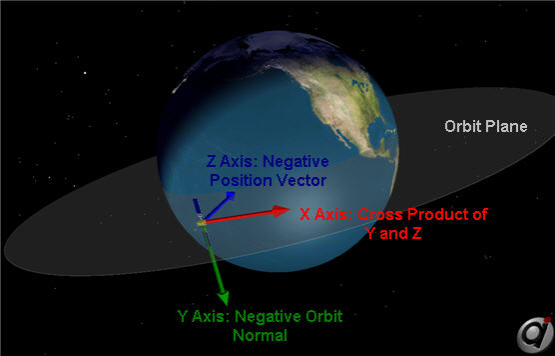
LVLH Attitude Reference Frame
VNB
The VNB (Velocity, Normal, Binormal) is a rotating reference frame that is described by:
•X-Axis: Vector oriented in the direction of v
•Y-axis: Vector oriented in the direction of the orbit normal, or in the direction of h
•Z-Axis: Oriented in the direction of r, forming a right-handed coordinate system
•Origin: Center of the Spacecraft
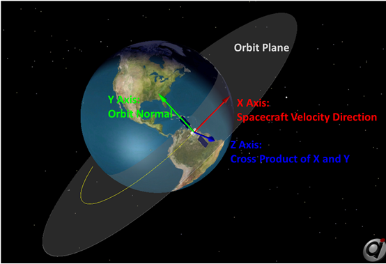
VNB Reference Frame
MJ2000 Earth Equator
The MJ2000 (Mean of Julian Date 2000) reference frame is an inertial reference frame (non-rotating) that is described by:
•Z-Axis: Vector normal to the mean equatorial plane at Julian year 2000.0, pointing towards the Northern Hemisphere
•X-Axis: Vector pointing from the center of Earth to the mean vernal equinox at Julian year 2000.0
•Y-Axis: Vector perpendicular to the x- and z- axes, forming a right-handed coordinate system
•Origin: Center of the Earth
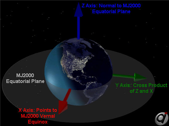
MJ2000 Reference Frame
Geodetic
The Geodetic reference frame is a rotating reference frame that is described by:
•Z-Axis: Vector normal to the Earth's surface in the direction of -r
•Y-axis: Negative to the orbit normal, or in the direction of -h
•X-Axis: Cross product of -h x -r, oriented in the direction of v
•Origin: Center of the Spacecraft
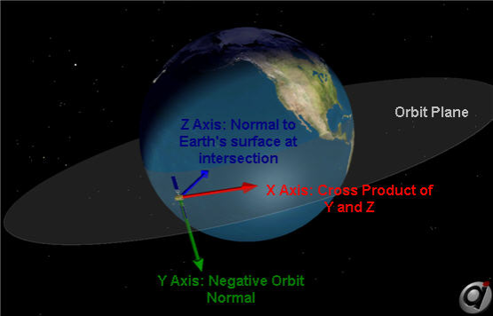
Geodetic Reference Frame
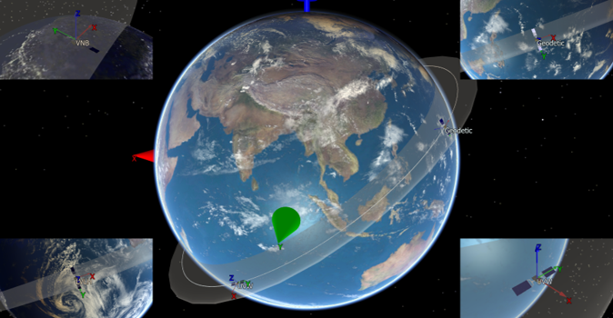
Let's use FreeFlyer to model the same spacecraft in different reference frames and check out the results.
LVLH vs Other Reference Frames
The LVLH - Earth Pointing Reference Frame is the default attitude reference frame in FreeFlyer. We are going to take a look at the differences between LVLH and a few of the other attitude reference frames, and show those differences in FreeFlyer.
LVLH vs Geodetic
The Geodetic frame is nearly the same as the LVLH frame. The difference is that the Geodetic frame's Z-axis is normal to the Earth's surface, not pointing to the center of the Earth like in the LVLH frame. The difference in these two frames is due to the shape of the Earth. The Earth is not a perfect sphere, it's an oblate spheroid, which you will get more into later in this guide. Therefore, the only time these frames line up are directly over the equator, and the north and south poles. By creating a spacecraft in FreeFlyer, and setting it's attitude reference frame to Geodetic, we can plot the spacecraft's attitude angles with respect to the LVLH frame. This shows that the frames are very similar, but due to the shape of the Earth, there are small differences in the attitude with respect to the LVLH frame.
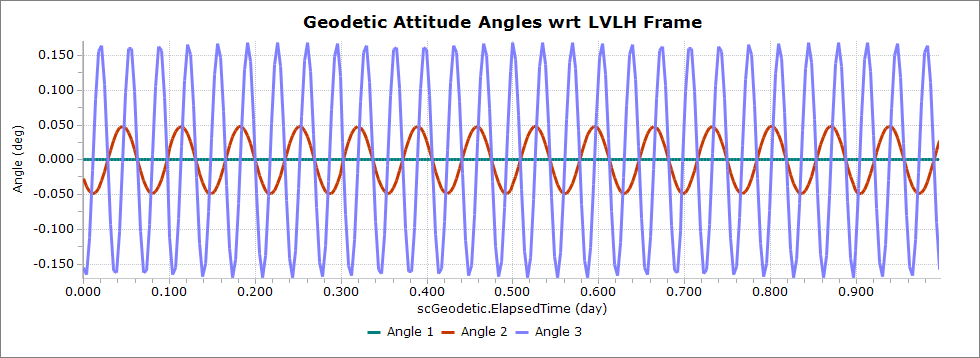
Attitude Angles with respect to the LVLH Frame
LVLH vs MJ2000
Here we are going to take a short look at the difference between the LVLH attitude reference frame and the MJ2000 attitude reference frame.
Problem: An important part of spacecraft operations is remote sensing, or the study of some quantity from a distance using a sensor on a spacecraft. Given a spacecraft model, we know our sensor is aligned along the Z-axis of the spacecraft body. Compare the results of attaching the same sensor to the same spacecraft, but in different reference frames. |
•Create a new Mission Plan and save it as "LVLHvsMJ2000.MissionPlan"
Adding in Spacecraft
•Add in two spacecraft objects through the object browser
•Double-click Spacecraft1 to bring up the editor window
•Rename it "scLVLH"
•Change the step size to 3 seconds
•On the left hand side navigate to Subsystems → Sensors
•Click "Create" to add a sensor to scLVLH. This creates a sensor pointed along the spacecraft Z-axis
•Click "Ok" to close the object editor and save your changes
•Click "Ok" again to save all changes and close the Spacecraft Editor
•Double-click Spacecraft2 to bring up the editor window
•Rename it to scMJ200
•Change the spacecraft's tail color to blue
•On the left hand side click "Attitude" → "Reference Frame" dropdown → Mean of J2000 Earth Equator
•On the left hand side navigate to Subsystems → Sensors
•Click "Create" to add a sensor to scMJ2000
•Click on Sensor1 in the Sensors page
•Click "Edit Sensor" under "Sensor1 - Properties"
•On the left hand side click visualization, and change the color to blue to match the spacecraft
•Click "Ok" to close the object editor and save your changes
Adding a ViewWindow
•Add in a ViewWindow through the object browser and open the ViewWindow Editor
•Under "Available Objects" check both spacecraft
•In the "Object Options" for both spacecraft:
oCheck Show Name
•Navigate over to Viewpoints on the left hand side
•Make the following changes to the default viewpoint
oUnder the "Source" dropdown change it to scLVLH
oClick "Copy to target"
oRight Ascension: 85 deg
oDeclination: -140 deg
oRaidus: 3000 km
Building the Mission Sequence
Before building the Mission Sequence, make sure your Object Browser looks like this:
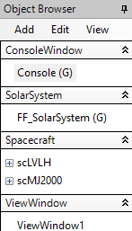
Object Browser Example
•Drag and drop a "While...End" loop into the Mission Sequence from the Script Elements
•Drag and drop a "FreeForm" segment inside the while loop and rename it "Step and Update"
•Open the FreeForm and type the following simple script.
Step scLVLH; Step scMJ2000 to (scMJ2000.Epoch == scLVLH.Epoch); Update ViewWindow1; |
Now our Mission Plan is ready to run! Your Mission Sequence should look something like this:
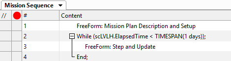
Mission Sequence Example
Run the mission plan and try to answer these questions:
Which attitude reference frame should be used if it's important to keep a sensor mounted to the Spacecraft body pointed directly toward the center of the Earth?
Which attitude reference frame should be used when pointing a camera mounted on the Spacecraft body at a distant star or galaxy?
LVLH vs VNB
In an eccentric orbit, the difference between these two frames will be a pitch rotation that is equal to the orbital flight path angle. For a circular orbit, the LVLH and VNB frames will be the same. Here we are going to take a look at this in FreeFlyer.
The flight path angle is defined as the angle measure from the local horizontal to the velocity vector. When the spacecraft is in orbit from perigee to apogee (outbound) the flight path angle is positive, and when the spacecraft is in orbit from apogee to perigee (inbound) the flight path angle is negative. At perigee and apogee the flight path angle is 0o, and it has a max value of 90o. The equation for solving the flight path angle is given by:
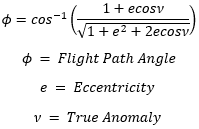
Flight Path Angle Equation
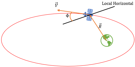
Flight Path Angle Diagram
Problem: Your company is launching a satellite in a highly elliptical orbit. You're tasked with the investigation of two different attitude reference frames: LVLH and VNB - so that the company can decide the most cost affective way of maintaining their desired attitude. |
Create a new Mission Plan and save it as "LVLHvsVNB.MissionPlan"
NOTE: This Mission Plan uses vectors for visualization and some calculations, but extensive knowledge of using vectors in FreeFlyer is not needed.
Adding in Spacecraft
•Create a Spacecraft with the following Keplerian elements:
oA: 18000 km
oE: 0.6
oI: 15 deg
oRAAN: 0 deg
oW: 0 deg
oTA: 0 deg
•In the top right corner of the object editor window, change the name to "scLVLH"
•Click "Propagator" on the left hand side and change the time step to 30 seconds
•Click "Ok" to close the editor and save your changes
•Right click scLVLH and clone it
•Rename the clone "scVNB"
•On the left hand side of the Spacecraft Editor click "Attitude"
•In the "Reference Frame" dropdown, select "VNB"
•Click "Ok" to close the editor and save your changes
Adding in ViewWindow Objects
•Add two ViewWindow Objects from the Object Browser
•Double click on ViewWindow1 to edit it, and rename it "closeUpView"
•Under "Available Objects" check both spacecraft
•In the "Object Options" for both spacecraft:
oCheck Show Name
•Navigate to "Viewpoints" on the left hand side
•Make the following changes to the Default Viewpoint
oSource: scLVLH
oClick "Copy to Target"
oRight Ascension: 45 deg
oDeclination: -130 deg
oRadius: 1750 km
•Click "Ok" to close out of the ViewWindow editor and save your changes
•Double click on ViewWindow2 to edit it, and rename it "orbitView"
•Under "Available Objects" check both spacecraft
•Under "Object Options", check the following for both spacecraft:
oShow Name
oShow History
oHistory Mode: Unlimited
•Navigate to "Viewpoints" on the left hand side
•Make the following changes to the Default Viewpoint
oReference Frame: Inertial
oSource: Earth
oClick "Copy to Target/Tail Ref."
oRight Ascension: 270 deg
oDeclination: 90 deg
oRadius: 75000 km
•Click "Ok" to close out of the ViewWindow editor and save your changes
Adding a PlotWindow
•Add a PlotWindow Object from the object browser
•Double click on PlotWindow1 to edit it, and rename it "deltaAngles"
•Under the "X-Axis" dropdown, select the "Choose an Object" dropdown and then select scVNB
•Make sure the "Choose a property or method" drop down is still "ElapsedTime"
•Click "More" on the right hand side to add one more series
•Click on the first series drop down
•Under the "Choose an object" drop down select scVNB
•Under the "Choose a property or method" drop down, scroll down and find "FPAngle". This is the orbital flight path angle
•Click on the next series drop down
•Under the "Choose an object" drop down select scVNB
•Under the "Choose a property or method" drop down, scroll down and find "AttitudeLVLH"
•In the "Enter an index value" box, type in the number 2. This is the scVNB's pitch rotation with respect to the LVLH frame
•Click "Ok" to close out of the PlotWindow editor and save your changes
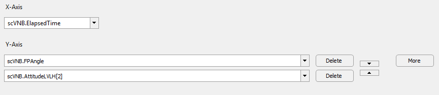
Plot Window Example
Building the Mission Sequence
Before building the Mission Sequence, make sure your Object Browser looks like this:
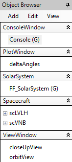
Object Browser Example
•Drag and drop a FreeForm script editor from the script elements into the mission sequence
•Rename this FreeForm "Vectors"
•Copy and paste the following script in this FreeForm, or follow this script breakdown to boost your knowledge of using Vectors in FreeFlyer
NOTE: These vectors will represent the Axes of the two spacecraft, and this script adjusts the color of the spacecraft and vectors to match.
•Create the 3 axes of each spacecraft as Vectors, and use the BuildVector method to set them as the axes of the two spacecraft
•Use the DrawMethod property to draw the vectors as arrows instead of lines when visualizing them in Outputs
•scLVLH will have yellow axes, so we do not need to change the color because the default vector color is yellow
•scVNB will have blue axes - use the ColorTools object to change the color to "CornflowerBlue"
// Create vectors for both spacecraft Vector XaxisLVLH; Vector YaxisLVLH; Vector ZaxisLVLH;
Vector XaxisVNB; Vector YaxisVNB; Vector ZaxisVNB;
// Build scLVLH vectors and draw them as arrows XaxisLVLH.BuildVector(4, scLVLH, 1); // X-body-axis vector YaxisLVLH.BuildVector(4, scLVLH, 2); // Y-body-axis vector ZaxisLVLH.BuildVector(4, scLVLH, 3); // Z-body-axis vector XaxisLVLH.DrawMethod = 1; YaxisLVLH.DrawMethod = 1; ZaxisLVLH.DrawMethod = 1;
// Build scVNB vectors and draw them as arrows XaxisVNB.BuildVector(4, scVNB, 1); // X-body-axis vector YaxisVNB.BuildVector(4, scVNB, 2); // Y-body-axis vector ZaxisVNB.BuildVector(4, scVNB, 3); // Z-body-axis vector XaxisVNB.Color=ColorTools.CornflowerBlue; YaxisVNB.Color=ColorTools.CornflowerBlue; ZaxisVNB.Color=ColorTools.CornflowerBlue; XaxisVNB.DrawMethod = 1; YaxisVNB.DrawMethod = 1; ZaxisVNB.DrawMethod = 1; |
•Add both vectors to the ViewWindow's we created and show their names - this must be done in script since we did not define the Vectors in the GUI
•Match the color of the Spacecraft objects to their respective vectors
// Add scLVLH vectors to the closeUpView and turn on vector names closeUpView.AddObject(XaxisLVLH); closeUpView.SetShowName("XaxisLVLH", 1); closeUpView.AddObject(YaxisLVLH); closeUpView.SetShowName("YaxisLVLH", 1); closeUpView.AddObject(ZaxisLVLH); closeUpView.SetShowName("ZaxisLVLH", 1);
// Add scVNB vectors the the closeUpView and turn on vector names closeUpView.AddObject(XaxisVNB); closeUpView.SetShowName("XaxisVNB", 1); closeUpView.AddObject(YaxisVNB); closeUpView.SetShowName("YaxisVNB", 1); closeUpView.AddObject(ZaxisVNB); closeUpView.SetShowName("ZaxisVNB", 1);
// Match spacecraft color to vector color scLVLH.Color = ColorTools.Yellow; // Default vector color is yellow scVNB.Color = ColorTools.CornflowerBlue; // Match color to vectors |
•Drag and drop a "While...End" after "Vectors"
• Change the while loop stopping condition to "scLVLH.ElapsedTime < TIMESPAN(14 hours)"
•Drag and drop a FreeForm inside the While loop, and rename it "Step, Report, Update"
The following script is very simple: we will step our spacecraft, sync their epochs, update the vector epochs, and update the outputs. Also, we need to report certain values to verify that the difference in these two frames is a change in pitch equal to the flight path angle at any given time. We can report scVNB's third Euler Angle with respect to the LVLH frame, as well as the flight path angle, and the angle between the two spacecraft's X-axes through the vectors we created earlier:
// Step sc and sync epochs Step scLVLH; Step scVNB to (scVNB.Epoch == scLVLH.Epoch);
// Update Vector epochs XaxisLVLH.Epoch = scLVLH.Epoch; YaxisLVLH.Epoch = scLVLH.Epoch; ZaxisLVLH.Epoch = scLVLH.Epoch;
XaxisVNB.Epoch = scLVLH.Epoch; // The epochs can be set to scLVLH because YaxisVNB.Epoch = scLVLH.Epoch; // scVNB's epoch is synced with scLVLH ZaxisVNB.Epoch = scLVLH.Epoch;
// Report and update outputs Report scVNB.AttitudeLVLH[2], scVNB.FPAngle, XaxisLVLH.VertexAngle(XaxisVNB); Update deltaAngles; Update closeUpView; Update orbitView; |
Now your mission plan is ready to run! The mission sequence should look like this:
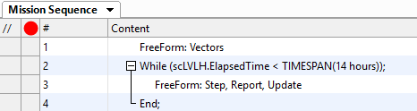
Mission Sequence Example
Save your progress and run to execute the Mission Plan. Then try to answer the following questions:
When are the X-axes of the two spacecraft oriented in the exact same direction?
What is the significance of the values on the plot?
Run the mission plan again but set the two spacecraft in circular orbits (e=0). What do you notice about these two frames? Why do you think that is happening?
We can also set a spacecraft's attitude reference frame to a custom reference frame using the CoordinateSystem object in FreeFlyer, and we will get more into this in the next tutorial.
See Also
•Next Topic: Mission Constraints on Spacecraft Attitude