A spacecraft's attitude is defined as its orientation in space, and the motion of a rigid spacecraft is defined by its position, velocity, attitude, and attitude motion. You previously learned in this guide the role position and velocity play into a spacecraft's motion; that is the position and velocity describe the inputs to compute the translational motion of the center of mass of the spacecraft (orbit). Attitude and attitude motion describe the rotational motion of the spacecraft about its center of mass. Spacecraft Attitude plays an important role in high-fidelity mission design; now we are going to look at the basics and model them in FreeFlyer.
There are different ways of numerically representing the attitude state of a spacecraft. The most common representations use Euler angles, quaternions, or a direction cosine matrix ("attitude matrix" in FreeFlyer). In FreeFlyer, these are referred to as the spacecraft's "attitude system." The Attitude System specifies the method FreeFlyer uses to orient a spacecraft with respect to the chosen reference frame.
In this section, we will discuss:
2.Calculating the Direction Cosine Matrix and Quaternions
3.Modeling the Direction Cosine Matrix and Quaternions
Euler Angles
Euler's rotation theorem states that any finite rotation of a rigid body can be expressed as a rotation through some angle about some fixed axis. Euler angle rotation is denoted by rotation angles φ, θ, ψ about coordinate axes i, j, and k respectively. The i-j-k Euler angle rotation means that the first rotation by angle φ is about the i-axis, then θ about the j-axis, and finally ψ about the k-axis. There are 12 different sequences for Euler angle rotation, and they are broken down into two types.
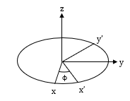
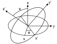
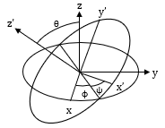
Euler Angle Diagram
Type 1 - In this case, each rotation takes place about 3 different axes. This type of rotation experiences a singularity at θ = ± 90°. A singularity is the loss of one degree of freedom in three-dimensional space. At these angles of θ, both φ and ψ have the exact same effect.
Type 2 - For this sequence, the first rotation occurs about some axis, then the second rotation occurs about another axis, and finally the third rotation occurs about the same axis as the first rotation. This rotation experiences a singularity at θ = 0° and 180°. Thus at these values of θ, both φ and ψ have the exact same effect.
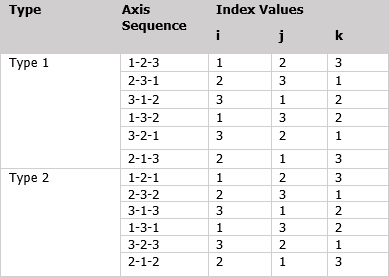
Euler Angle Sequences
Let's take a look at some of these sequences and model them using FreeFlyer.
Problem: A start-up company wants to launch a remote sensing satellite to study Earth. They've hired you to demonstrate to them the use of Euler Angles to manipulate a spacecraft's attitude so they can learn how to align their sensor properly. |
•Create a new mission plan and save it as "EulerAngles.MissionPlan"
Adding in Spacecraft
•Add a Spacecraft object from the Object Browser on the left hand side of the control screen
•Double-click on Spacecraft1
•In the Orbit section of the Spacecraft Editor navigate to "Element Type"
•Click the dropdown and select "Keplerian"
•Give the Spacecraft the following Keplerian elements:
oA: 8000 km
oE: 0
oI: 30 deg
oRAAN: 0 deg
oW: 0 deg
oTA: 0 deg
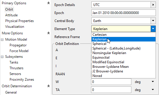
Keplerian Elements Dropdown
•Right click Spacecraft1 and rename it to "scConstantAttitude".
•Click on "Attitude" in the left hand side of the Spacecraft Editor under "Primary Options", and give scConstantAttitude the following properties:
oReference Frame: LVLH - Earth Pointing
oAttitude System: Euler Angles
oRotation Sequence: 1-2-3
oEuler Angles and Rates: 0
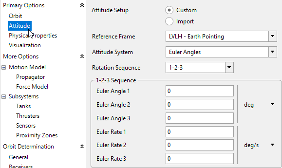
Attitude Tab in the Spacecraft Editor
•Click "Propagator" on the left hand side and change the step size to 3 seconds.
•Click "Ok" to close the spacecraft editor
•Right-click scConstantAttitude and clone it three times
•Double-click "scConstantAttitude_Copy1" and rename it "scRoll"
•Under scRoll attitude tab, change the "Euler Rate 1" to 0.08 deg/s
•Double-click "scConstantAttitude_Copy2" and rename it "scPitch"
•Under scPitch attitude tab, change the "Euler Rate 2" to 0.08 deg/s
•Double-click "scConstantAttitude_Copy3" and rename it "scYaw"
•Under scYaw attitude tab, change the "Euler Rate 3" to 0.08 deg/s
Adding in multiple ViewWindow objects
•Add a ViewWindow object through the Object Browser
•Open the ViewWindow editor by double-clicking "ViewWindow1"
•In the top right change the name to "viewConstantAttitude"
•Check scConstantAttitude under the "Available Objects" section
•Under scConstantAttitude "Object Options" section:
oCheck Show Name
oUncheck Show History
oCheck Show Axes
•Navigate over to the Viewpoints tab on the left-hand side
•Make sure the Reference Frame is checked as "body-fixed"
•In the "Source" drop-down, change the source to scConstantAttitude
•Click "Copy to Target"
•Change the following properties of the Default Viewpoint:
oRight Ascension: 12 deg
oDeclination: -135 deg
oRadius: 1250 km
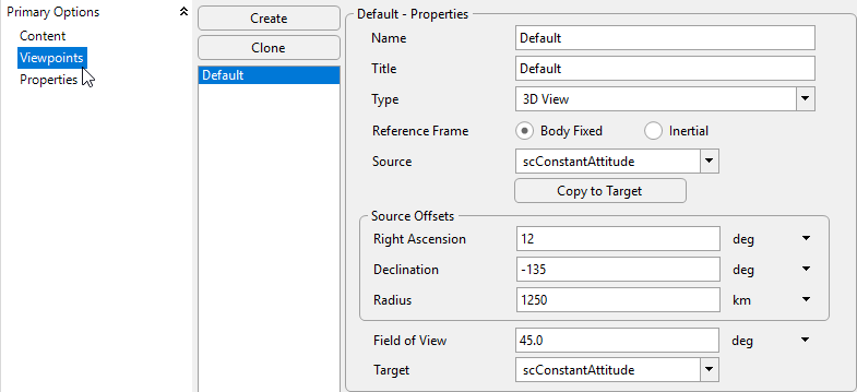
Viewpoint for viewConstantAttitude
•Click "Ok" to close the ViewWindow editor
•Right-click "viewConstantAttitude" and clone it three times
•Double-click "viewConstantAttitude_Copy1" and rename it "viewRoll"
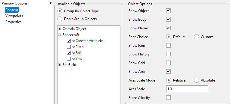
•In the "Available Objects" section:
oKeep scConstantAttitude checked
oCheck scRoll
•In the "Object Options" section for scConstantAttitude uncheck "Show Object"
•In the "Object Options" section for scRoll:
oCheck Show Name
oUncheck Show History
oCheck Show Axes
•Double-click "viewConstantAttitude_Copy2" and rename it "viewPitch"
•In the "Available Objects" section:
oKeep scConstantAttitude checked
oCheck scPitch
•In the "Object Options" section for scConstantAttitude uncheck "Show Object"
•In the "Object Options" section for scPitch:
oCheck Show Name
oUncheck Show History
oCheck Show Axes
•Double-click "viewConstantAttitude_Copy3" and rename it "viewYaw"
•In the "Available Objects" section:
oKeep scConstantAttitude checked
oCheck scYaw
•In the "Object Options" section for scConstantAttitude uncheck "Show Object"
•In the "Object Options" section for scYaw:
oCheck Show Name
oUncheck Show History
oCheck Show Axes
Example for ViewWindow viewRoll
Building the Mission Sequence
Before building the Mission Sequence, make sure your Object Browser looks like this:
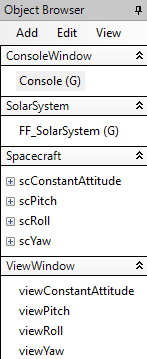
Object Browser Example
•From the Script Elements browser, drag and drop a "While...End" loop into the Mission Sequence
•Change the while loop stopping condition to "scConstantAttitude.ElapsedTime < TIMESPAN(1.5 hours)"
•From the Script Elements browser, drag and drop a FreeForm script editor inside the while loop
•Double click the FreeForm script editor and change its name to "Step and Update"
The following script is relatively simple, we just need to step our spacecraft, synchronize their epochs, and update each ViewWindow. It should look something like this:
// Step each Spacecraft and sync their Epochs Step scConstantAttitude; Step scRoll to (scRoll.Epoch == scConstantAttitude.Epoch); Step scPitch to (scPitch.Epoch == scConstantAttitude.Epoch); Step scYaw to (scYaw.Epoch == scConstantAttitude.Epoch);
// Update each ViewWindow Update viewConstantAttitude; Update viewRoll; Update viewPitch; Update viewYaw; |
Now our Mission Plan is ready to run! Your Mission Sequence should look something like this:
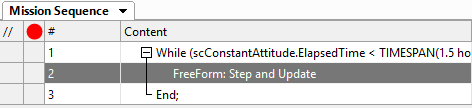
Mission Sequence Example
Save your progress and then run to execute the Mission Plan. Then, try to answer these questions:
What is the significance of Roll, Pitch, and Yaw?
Run the mission plan again, but change scYaw's Rotation Sequence to 3-2-1. Which two Spacecraft now have identical attitude motion?
Bonus: Modeling a Singularity
Let's talk more about the singularity we mentioned at the beginning of this section. This singularity, also known as Gimbal Lock, is the loss of one degree of freedom in 3D space. Therefore, two of the rotations will have the exact same effect on the body for certain values of θ that we discussed earlier. Let's take a look at Type-1 sequences and model a singularity in FreeFlyer.
Keep "EulerAngles.MissionPlan" open
Changing a Spacecraft
•Double-click on scRoll to change its properties
•Under the Attitude tab:
oKeep the 1-2-3 sequence
oEuler Angle 1: 0 deg
oEuler Angle 2: 90 deg
oEuler Angle 3: 0 deg
oEuler Rate 1: 0.08 deg/s
oEuler Rate 2: 0 deg/s
oEuler Rate 3: 0.08 deg/s
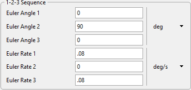
scRoll new Attitude Properties
•Run to execute the Mission Plan and examine scRoll
Notice how scRoll is pitched upwards by 90° but only rotating about one axis. Why is this? We made sure that both Euler Angle 1 and Euler Angle 3 are both rotating. This is the singularity we discussed earlier. Since θ is rotated 90°, both φ and ψ have the same effect. That is why it appears scRoll is rotating twice as fast as the other spacecraft, because two 0.08 deg/s rotation rates are applied in the same direction due to the singularity.
Calculating the Direction Cosine Matrix and Quaternions
There are other ways of representing a spacecraft's attitude. Here we will discuss the significance of the Direction Cosine Matrix along with Quaternions, and the math behind calculating these values for a given attitude state. Starting with a given set of Euler Angles, we will perform our own calculations in order to analyze the same spacecraft attitude in three different representations.
Problem: We are performing the initial attitude analysis on a future satellite project. Our goal is to take the planned Euler Angle rotations and perform hand calculations of the Direction Cosine Matrix and Quaternion. We need to verify our hand calculations are correct, and visualize the spacecraft's attitude in FreeFlyer. Our spacecraft will have a 3-1-2 sequence with rotations: φ = 20 degrees, θ = 35 degrees, and ψ = 45 degrees. |
Direction Cosine Matrix
Given an orthogonal, right handed triad u, v, and w of unit vectors fixed in the body frame, such that u x v = w, we can specify the components of u, v, and w along the three axes of the body frame so that the body frame is fixed completely with respect to the reference frame. This sets up a 3x3 matrix with 9 parameters, A, called the attitude matrix:
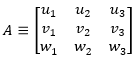
Attitude Matrix
Each of these elements is the cosine of the angle between the body frame unit vector and the reference axis. For example, u₂ is the cosine of the angle between u and the reference 2 axis. Because of this, A is often referred to as the direction cosine matrix. The direction cosine matrix, or DCM, is a coordinate transformation that maps vectors from the reference frame to the body frame. Some properties of the DCM:
![]()
Properties of the DCM
These properties mean that the DCM is a real orthogonal matrix; therefore the transpose of A maps vectors from the body frame back to the reference frame. It is possible to calculate the direction cosine matrix from Euler Angles. Each individual Euler Angle Rotation about a reference axis has its own DCM. For an arbitrary angle φ, the Euler rotations about reference axes 1, 2, and 3 are:
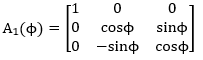
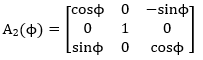
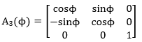
Direction Cosine Matrices for Individual Rotations
The direction cosine matrix for the overall rotation sequence is the matrix product of each of the individual rotation matrices shown above, with the first rotation matrix on the right and the last rotation matrix on the left as shown by this equation:
![]()
Equation for Calculating DCM
We are going to calculate the DCM for a 3-1-2 Euler Sequence. Following the equation above, for a 3-1-2 sequence we have:
NOTE: Every Euler angle rotation sequence has its own DCM; this is the DCM for a 3-1-2 rotation.
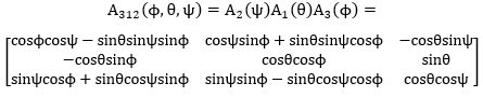
Direction Cosine Matrix for a 3-1-2 Euler Sequence
Our Spacecraft is going to have rotations of φ = 20 degrees, θ = 35 degrees, and ψ = 45 degrees. Performing hand calculations by plugging in the values into the matrix above we get:
![]()
Results of Hand Calculations
We will use these values to model our Spacecraft's attitude in the next section of this tutorial. For now, let's talk about quaternions.
Quaternions
The DCM can also be parameterized in terms of Euler symmetric parameters. These four parameters are not independent, but satisfy the constraint equation:
![]()
Constraint Equation
Euler symmetric parameters make up the elements of the quaternion providing a redundant, non-singular attitude description that is well suited to describe arbitrary, large rotations. Quaternions are made up of four parameters: the three components of a vector and a scalar. The vector component of the quaternion describes an axis between a reference frame and the body frame of the vehicle, and the scalar component gives the rotation about that axis. The components of a quaternion are:
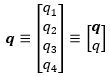
Quaternion Representation
Also represented by:
![]()
Quaternion Representation
Where i, j, and k are the hyperimaginary numbers satisfying the conditions:
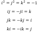
Hyperimaginary Numbers
The quantity, q₄ , is the real or scalar part of the quaternion, and iq₁ + jq₂ + kq₃ is the imaginary or vector part. Now let's calculate the Quaternion from the DCM we previously calculated.
The components of a quaternion with respect to a DCM can be calculated by the following equations:
NOTE: There is a sign ambiguity in the calculations, because changing the signs of all the components of the quaternion simultaneously does not affect the DCM. There are 4 possible ways of calculating the components of the quaternion. All methods are mathematically equivalent, but error can be reduced by avoiding calculations in which the component of the quaternion appearing in the denominator is close to zero. For our analysis, we will just use the following equations.
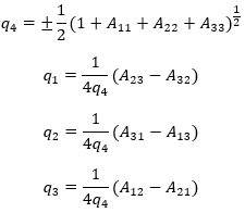
Quaternion calculations from DCM
Plugging in the elements of the DCM we previously calculated, the components of the 3-1-2 sequence should be:
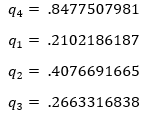
Results of Hand Calculations
Of course we can also use FreeFlyer script to calculate these values, and compare them to the values stored in the Spacecraft object. The following script breakdown demonstrates the manual calculations for a 3-1-2 rotation sequence:
•Create the rotation angles as Variables, and assign them to the Spacecraft object's AttitudeAngles property
// Calculations for a 3-1-2 rotation Variable phi; Variable theta; Variable psi;
// Assign Euler Angles phi = Spacecraft1.AttitudeAngles[0]; theta = Spacecraft1.AttitudeAngles[1]; psi = Spacecraft1.AttitudeAngles[2]; |
•Create a matrix and enter each element from the DCM for a 3-1-2 sequence in variable form that we found earlier
Matrix dcm312;
// Calculate the DCM by hand dcm312 = [cos(rad(psi))*cos(rad(phi))-sin(rad(psi))*sin(rad(theta))*sin(rad(phi)), cos(rad(psi))*sin(rad(phi))+cos(rad(phi))*sin(rad(psi))*sin(rad(theta)), -cos(rad(theta))*sin(rad(psi)); -cos(rad(theta))*sin(rad(phi)), cos(rad(theta))*cos(rad(phi)), sin(rad(theta)); sin(rad(psi))*cos(rad(phi)) + cos(rad(psi))*sin(rad(theta))*sin(rad(phi)), sin(rad(psi))*sin(rad(phi))-sin(rad(theta))*cos(rad(psi))*cos(rad(phi)), cos(rad(psi))*cos(rad(theta))]; |
•Calculate the quaternion by creating an array and assigning each element to the four components of the quaternion and the necessary equations to solve for them
•Create a Report command so that we can compare our calculations and equations to the values that FreeFlyer has calculated
Array q[4];
Calculate the quaternion by hand q[3] = .5*sqrt((1+ dcm312[0,0] + dcm312[1,1] + dcm312[2,2])); q[0] = 1/(4*q[3])*(dcm312[1,2] - dcm312[2,1]); q[1] = 1/(4*q[3])*(dcm312[2,0] - dcm312[0,2]); q[2] = 1/(4*q[3])*(dcm312[0,1] - dcm312[1,0]);
Report dcm312, Spacecraft1.AttitudeMatrix, q, Spacecraft1.Quaternion; |
Now we'll compare these hand-calculated values to FreeFlyer's built in conversions.
Modeling the Direction Cosine Matrix and Quaternions
We discussed how to find the DCM and Quaternion by hand - now let's take a closer look at their physical meaning by modeling them in FreeFlyer. Keep your hand calculations close as we will be using them in the following Mission Plan!
Create a new Mission Plan and save it as "ModelQuaternionDCM.MissionPlan"
Adding in Spacecraft
•Create a Spacecraft with the following Keplerian elements:
oA: 15000 km
oE: 0.4
oI: 15 deg
oRAAN: 0 deg
oW: 0 deg
oTA: 0 deg
•Rename the Spacecraft to "scEuler".
•Click on "Attitude" in the left hand side of the Spacecraft Window under "Primary Options", and give scEuler the following properties:
oReference Frame: LVLH - Earth Pointing
oAttitude System: Euler Angles
oRotation Sequence: 3-1-2
oEuler Angle 1: 20
oEuler Angle 2: 35
oEuler Angle 3: 45
•Click on "Propagator" on the left hand side and change the step size to 0.5 seconds.
•Click “Ok” to save your changes and close the Spacecraft Editor
•Right-click on scEuler and clone it twice.
•Double click on "scEuler_Copy1" and rename it "scDCM"
•Click on "Attitude" on the left hand side of the Spacecraft Editor
•Under the "Attitude System" dropdown, select "Attitude Matrix"
•Fill in the Matrix with the values we calculated by hand
•Click “Ok” to save your changes and close the Spacecraft Editor
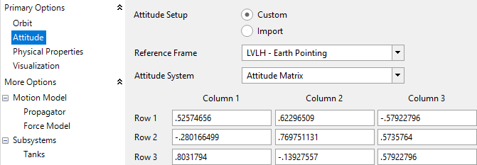
scDCM Attitude Properties
•Double click on "scEuler_Copy2" and rename it "scQuaternion"
•Click on "Attitude" on the left hand side of the Spacecraft Editor
•Under the "Attitude System" dropdown, select "Quaternion"
•Fill in the components of the quaternion with the values we calculated by hand
•Click “Ok” to save your changes and close the Spacecraft Editor
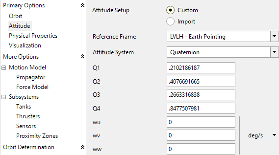
scQuaternion Attitude Properties
•Right click on "scQuaternion" and clone it
•Rename the clone to "scRotating"
•Click on "Attitude" on the left hand side of the Spacecraft Editor
•Give scRotating the following rotation rates:
owu: 1.006 deg/s
owv: 0.008 deg/s
oww: 0.06 deg/s
•Click “Ok” to save your changes and close the Spacecraft Editor
Adding a ViewWindow
•Add a ViewWindow through the object browser and rename it "threeDView"
•Under "Available Objects" check all four spacecraft
•In the "Object Options" for all four spacecraft:
oCheck Show Name
oCheck Show History
oCheck Show Axes
•Navigate to Viewpoints
•Make the following Changes to the Default ViewPoint
oIn the "Source" dropdown scroll down and click scEuler, then click "Copy to Target"
oRight Ascension: 315 deg
oDeclination: -55 deg
oRadius: 930 km
•Click "Ok" to save your changes and close the ViewWindow Editor
Adding a PlotWindow
•Add a PlotWindow through the object browser and rename it "plotQuaternion"
•Click on the X-Axis dropdown menu
•Under "Choose an object", click the dropdown and select scRotating
•Under the "Choose a property or method", click the dropdown and select "ElapsedTime"
•Click on the Y-Axis dropdown menu
•Under "Choose and object", click the dropdown and select scRotating
•Under "Choose a property or method", select "Quaternion"
•Leave the "0" under "Choose an index value"
•Click "More" 3 times to add the other components of the quaternion
•Click on the second Y-Axis dropdown
•Under "Choose and object", click the dropdown and select scRotating
•Under "Choose a property or method", select "Quaternion"
•Enter "1" in the "Choose an index value" box
•Repeat this for the other components of the quaternion
•Your PlotWindow Editor should look like this:
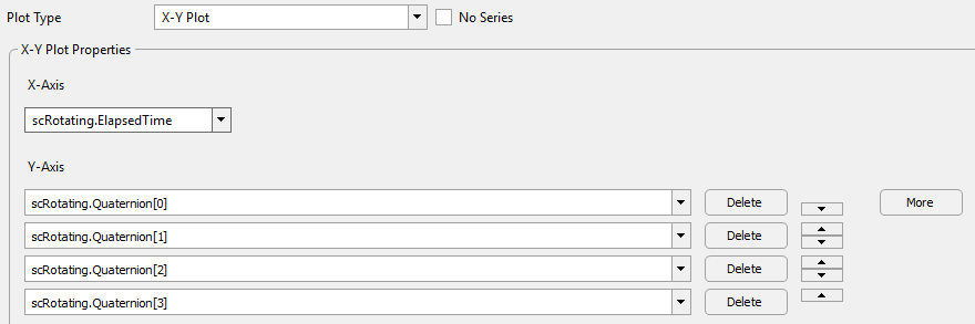
PlotWindow Editor Example
•Click "Ok" to save your changes and close the PlotWindow Editor
Building the Mission Sequence
Before building the Mission Sequence, make sure your Object Browser looks like this:
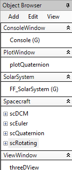
Object Browser Example
•From the Script Elements browser on the right hand side of the control screen , drag and drop a "While...End" loop into the Mission Sequence
•Change the while loop stopping condition to "scEuler.ElapsedTime < TIMESPAN(30 minutes)"
•From the Script Elements browser, drag and drop a FreeForm script editor inside the while loop
•Double click the FreeForm script editor and change its name to "Step and Update"
•We will also be adding a Watch command to create a WatchWindow that will report the value of scRotating's quaternion components at every time step
The following script is relatively simple, we just need to step our spacecraft, synchronize their epochs, add the Watch command, and update the other outputs:
// Step Spacecraft and Synch Epochs Step scEuler; Step scQuaternion to (scQuaternion.Epoch == scEuler.Epoch); Step scDCM to (scDCM.Epoch == scEuler.Epoch); Step scRotating to (scRotating.Epoch == scEuler.Epoch);
// Watch command Watch scRotating.Quaternion[0], scRotating.Quaternion[1], scRotating.Quaternion[2], scRotating.Quaternion[3];
// Update Outputs Update threeDView; Update plotQuaternion; |
Also, let's verify that our hand calculations from earlier were correct
•From the Script Elements browser, drag and drop a FreeForm script editor before the while loop
•Double click the FreeForm script editor and change its name to "Check Calculations"
The following script will report the DCM and Quaternion of scEuler, which means FreeFlyer is calculating the DCM and Quaternion from the Euler Angles that we input into scEuler
Report scEuler.AttitudeMatrix, scEuler.Quaternion; |
Now the Mission Plan is ready to run! It should look something like this:
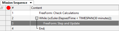
Mission Sequence Example
Save your progress and then run to execute the Mission Plan. Then, try to answer these questions:
In the threeDView output - why does it appear that there is a single rotating spacecraft and a single stationary spacecraft?
Did your hand calculated values match what FreeFlyer calculated?
Inspect the generated WatchWindow and the plotQuaternion plot - do you notice something significant about the components of the quaternion at all times?
See Also
•Next Topic: Attitude Reference Frames