The most important part of mission design is the mission itself. There are hundreds of spacecraft and satellite missions, and each has varying requirements. Sometimes we want to point our spacecraft towards the Sun, or point to the ground for communications, or point to the Earth or to space for science.
In FreeFlyer, it is possible to design your own custom attitude reference frame with the use of Vector and CoordinateSystem objects. We can choose a primary vector that we want to point the spacecraft body toward, and then a secondary vector that will define the rotation about the primary vector. This is also referred to as "align and constrain".
In this section we will discuss:
1.Custom Mission Attitude Frame
Custom Mission Attitude Frame
In the previous sections we have discussed different ways to represent a spacecraft's attitude, and how those representations can change with the variety of reference frames. Now, let's put it all together with a mission design problem.
Problem: A GEO satellite is equipped with 40% efficient solar panels that have a total area of 6.5m2 aligned with the Z-axis. Its mission requires that it constantly looks to the Canberra ground station in Australia with a sensor along the X-axis, and that it must have at least 1000W of power supplied at all times. We must create a custom attitude reference frame that meets these requirements. |
Create a new Mission Plan and save it as "CustomMissionFrame.MissionPlan"
Adding in a Spacecraft with a Sensor
•Create a Spacecraft with the following Keplerian elements:
oA: 42164 km
oE: 0
oI: 30 deg
oRAAN: 210 deg
oW: 15 deg
oTA: 0 deg
•Change the Spacecraft tail color to green
•Change the step size to 30 seconds
•On the left hand side of the editor window under "Subsystems" click "Sensors"
•Click "Create" to create a sensor for the Spacecraft, then click "Edit"
•On the "Sensor Properties" page, change the "Cone Half Angle" to 2.5 degrees
•Under the "Orientation wrt Spacecraft BCS" click the "System" dropdown, and select "Unit Vector"
•In the "NX" box enter 1, and in the "NZ" box enter 0
•On the left hand side of the Object Editor click "Visualization"
•On that page, change the color to green to match the Spacecraft
•In the "Projection Height" box enter 42164 km
•Click "Ok" to save your changes and click "Ok" again to save your changes and close the Spacecraft Editor
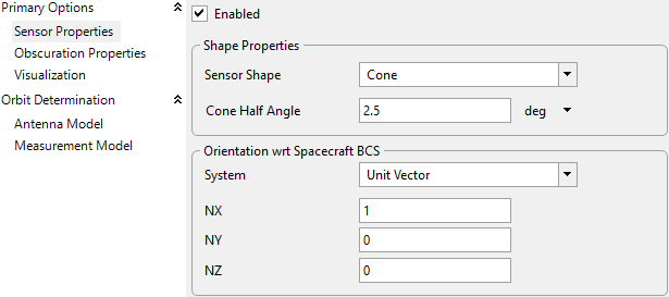
Sensor Properties
•Add in a GroundStation through the object browser and double-click the GroundStation to edit it
•On the "Properties" Page where it says "GroundStation Setup" click "Station Geodetics File"
•In the "Station Data" box click the "Station Acronym" dropdown and select "DS45 - Canberra Australia"
•Navigate to "Visualization" on the left hand side and change the color to blue
•Click "Ok" to save your changes and close the GroundStation Editor
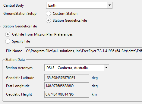
Canberra GroundStation
Adding in Vector, Variable, and CoordinateSystem Objects
•In the Object Browser click "Add"
•Under the "Variable" section that has multiple options:
•Add in 6 Variable, 3 Vector, and 1 CoordinateSystem Objects and name them the following:
NOTE: After adding an object you can hit CTRL+SHIFT+Y to continue adding the most recently added object type, also you can use F2 as a shortcut to rename objects
•Vectors:
oscToCanberra
oscToSun
osolarPanelVec
•Variables:
omeanSunDist
opanelAngle
opanelArea
opanelEfficiency
opanelPower
osolarFlux
•Coordinate System:
omissionFrame
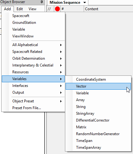
Adding Vectors and Variables through Object Browser
Adding in Multiple ViewWindow Objects
•Add two ViewWindow Objects from the Object Browser
•Double click on ViewWindow1 to edit it, and rename it "earthView"
•Check Spacecraft1
•Under "Object Options", check the following:
oShow Name
oShow History
oHistory Mode: Unlimited
•Check Canberra
•Under "Object Options", check the following
oShow Name
•Check Vectors scToCanberra and scToSun
•Navigate to "Viewpoints" on the left hand side
•Make the following changes to the Default Viewpoint
oReference Frame: Inertial
oSource: Earth
oClick "Copy to Target/Tail Ref."
oRight Ascension: 130 deg
oDeclination: 30 deg
oRadius: 95000 km
•Click "Ok" to close out of the ViewWindow editor and save your changes
•Double click on ViewWindow2 to edit it, and rename it "scView"
•Check Spacecraft1
•Under "Object Options", check the following:
oShow Name
•Check Canberra
•Under "Object Options", check the following
oShow Name
•Check Vectors scToCanberra and scToSun
•Navigate to "Viewpoints" on the left hand side
•Make the following changes to the Default Viewpoint
oReference Frame: Inertial
oSource: Spacecraft1
oClick "Copy to Target/Tail Ref."
oRight Ascension: 200 deg
oDeclination: 0 deg
oRadius: 800 km
•Click "Ok" to close out of the ViewWindow editor and save your changes
Adding in a PlotWindow
•Add a PlotWindow Object from the object browser
•Double click on PlotWindow1 to edit it, and rename it "powerPlot"
•Click the "Y-Axis" dropdown, and in the "Choose which type of item to use" dropdown select "Object"
•Click the "Choose an object:" dropdown and choose panelPower
•Click "Ok" to close the PlotWindow editor and save your changes
Prior to building the Mission Sequence we must set our Spacecraft's attitude reference frame to the custom one we just created
•Double click Spacecraft1 to edit it
•On the left hand side, go into the "Attitude" options
•In the "Reference Frame" dropdown select "Custom Coordinate System"
•A new dropdown will appear called "Coordinate System", click it and select our custom CoordinateSystem "missionFrame"
•Click "Ok" to close the Spacecraft editor and save your changes
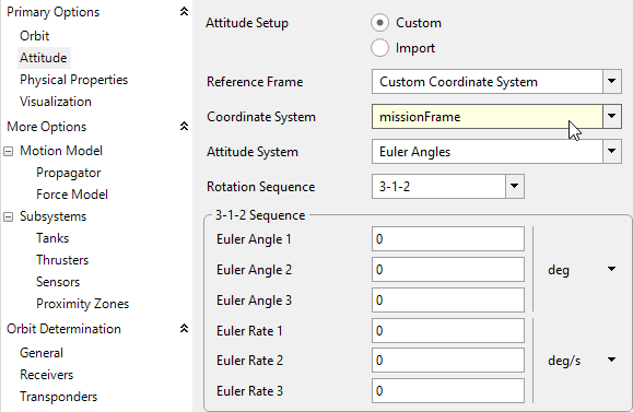
Using a Custom Coordinate System as a Reference Frame
Building the Mission Sequence
•Drag and drop a FreeForm script editor from the script elements into the mission sequence
•Rename this FreeForm "Initialize Variables"
First, we are going to build our vectors. The BuildVector method in FreeFlyer allows us to define a vector in many ways. First we must select the vector type we want; in this case we will use Object-to-Object and Body Axis vectors. For an Object-to-Object vector we must define the origin object, and then the reference object that the vector will point to. For a Body Axis vector, we will choose our Spacecraft, and then which body axis we want, in this case the Z-Axis for the solar panel normal vector. Then, we will use those two vectors to build our custom CoordinateSystem. We will define the CoordinateSystem X-axis as the vector that points from our Spacecraft to the GroundStation, then we will define the CoordinateSystem Z-axis to be constrained toward the vector that points from our Spacecraft to the Sun. Finally, we will input values for a few of our variables.
Type the following script into this FreeForm:
NOTE: Take a look at a few of the different possible overloads for Vector and CoordinateSystem objects to see the many options FreeFlyer offers
// Vectors scToSun.BuildVector(9,Spacecraft1,Sun); // Object-to-Object vector scToCanberra.BuildVector(9, Spacecraft1, Canberra); // Object-to-Object vector solarPanelVec.BuildVector(4,Spacecraft1,3); // Z-body-axis vector
// Coordinate System missionFrame.BuildCoordinateSystem(1,scToCanberra,3,scToSun);
// Variables solarFlux = 1366.7; // W/m^2 meanSunDist = 149530000; // m panelArea = 6.5; // m^2 panelEfficiency = .40; // No units |
•Drag and drop a "While...End" loop into the Mission Sequence after the first FreeForm
•Drag and drop a FreeForm script editor inside the while loop and name it "Solar Power Calculation"
Here we are going to calculate the power from our solar panels. The equation for that calculation is:
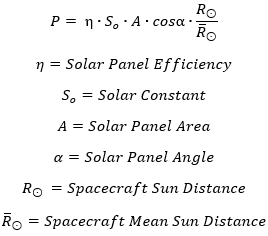
Solar Power Equation
It is important to note that the panel angle must be between 0 and 90 degrees for the panels to receive any sunlight. We will address this in the following FreeForm with an "If" statement. Write the following script in this FreeForm:
// Solar Power Calculation
// Define Panel Angle so it updates with time panelAngle = solarPanelVec.VertexAngle(scToSun); // deg
// The Panel Angle must be between 0 and 90 degrees for the solar panels to be in contact with sunlight If (0 < solarPanelVec.VertexAngle(scToSun) and solarPanelVec.VertexAngle(scToSun) < 90) then; panelPower = panelEfficiency*solarFlux*panelArea*cos(rad(panelAngle))*Spacecraft1.SCSunDistance/meanSunDist; // W Else; panelPower = 0; End; |
•Drag and drop another FreeForm script editor after our calculations
•Name it "Step and Update"
Here we are going to Step our Spacecraft, sync Epochs, and Update our outputs. Type the following simple script into the FreeForm:
// Step and Update
// Sync Vector Epochs with Spacecraft Epoch scToCanberra.Epoch = Spacecraft1.Epoch; scToSun.Epoch = Spacecraft1.Epoch; solarPanelVec.Epoch = Spacecraft1.Epoch;
// Update Outputs Update earthView; Update scView; Update powerPlot;
// Step Spacecraft Step Spacecraft1; |
Now your mission plan is ready to run! The mission sequence should look like this:
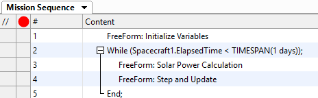
Mission Sequence Example
Save your progress and run to execute the Mission Plan. Then try and answer the following questions:
Take a look at the graph. What are the minimum and maximum power values? Do they meet the mission requirements?
Notice the scView ViewWindow, what is the significance of the scToSun Vector?
Run the mission plan again but set the Spacecraft attitude to LVLH - Earth Pointing, do we still meet mission requirements?
See Also
•Previous Topic: Attitude Reference Frames