When making planetary flybys or rendezvous, many missions will use what is called "B-Plane Targeting." This allows the spacecraft to have a specific hyperbolic trajectory past the planet. This is useful when attempting to fly past a specific geographical location on a planet, or making the capture orbit a specific inclination.
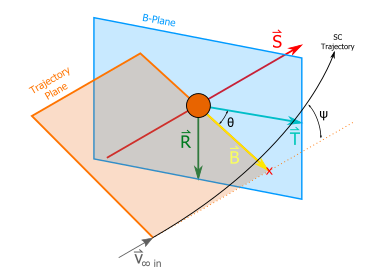
But what exactly is the B-plane? The B-plane is a plane that is orthogonal to the hyperbolic trajectory plane and the initial hyperbolic excess velocity vector. This is typically described with a vector, B, and an angle, Θ, to help define the hyperbolic trajectory in 3D space. Also, there are three orthogonal unit vectors R, S, and T, to help calculate these values.
In this section, we will discuss:
Calculating the B-Plane
If we have the velocity vector and the radius vector at the orbit periapsis, we can solve for the B vector, and the angle Θ.
The B vector points to where the asymptote of the hyperbolic trajectory pierces the B-plane. It may be easier to visualize this as where the spacecraft would pierce the B-plane if it ignored the planet's gravity. The angle 'Θ' is the angle between the 'B' vector, and the 'T' unit vector. The 'T' unit vector is, along with the R unit vector, an axis of the B-Plane.
B-Plane Diagram
To find B and Θ, we must find a few unit vectors to make our calculations easier.
The first unit vector is 'S'. This is the direction of the hyperbolic excess velocity at the entry of the sphere of influence.
The second unit vector is 'T'. This is the orthogonal axis to the 'S' unit vector, and the normal of the planet. It also typically lies on the ecliptic plane of the solar system.
The third unit vector is 'R'. This is simply the cross product of 'S' and 'T'.
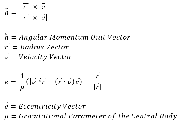
But if all we're given is an initial state vector, how can we calculate these things? The first step is to calculate the angular momentum vector and the eccentricity vector.
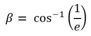
Next, we need to calculate our semi-major axis, and our beta angle. This is simply:
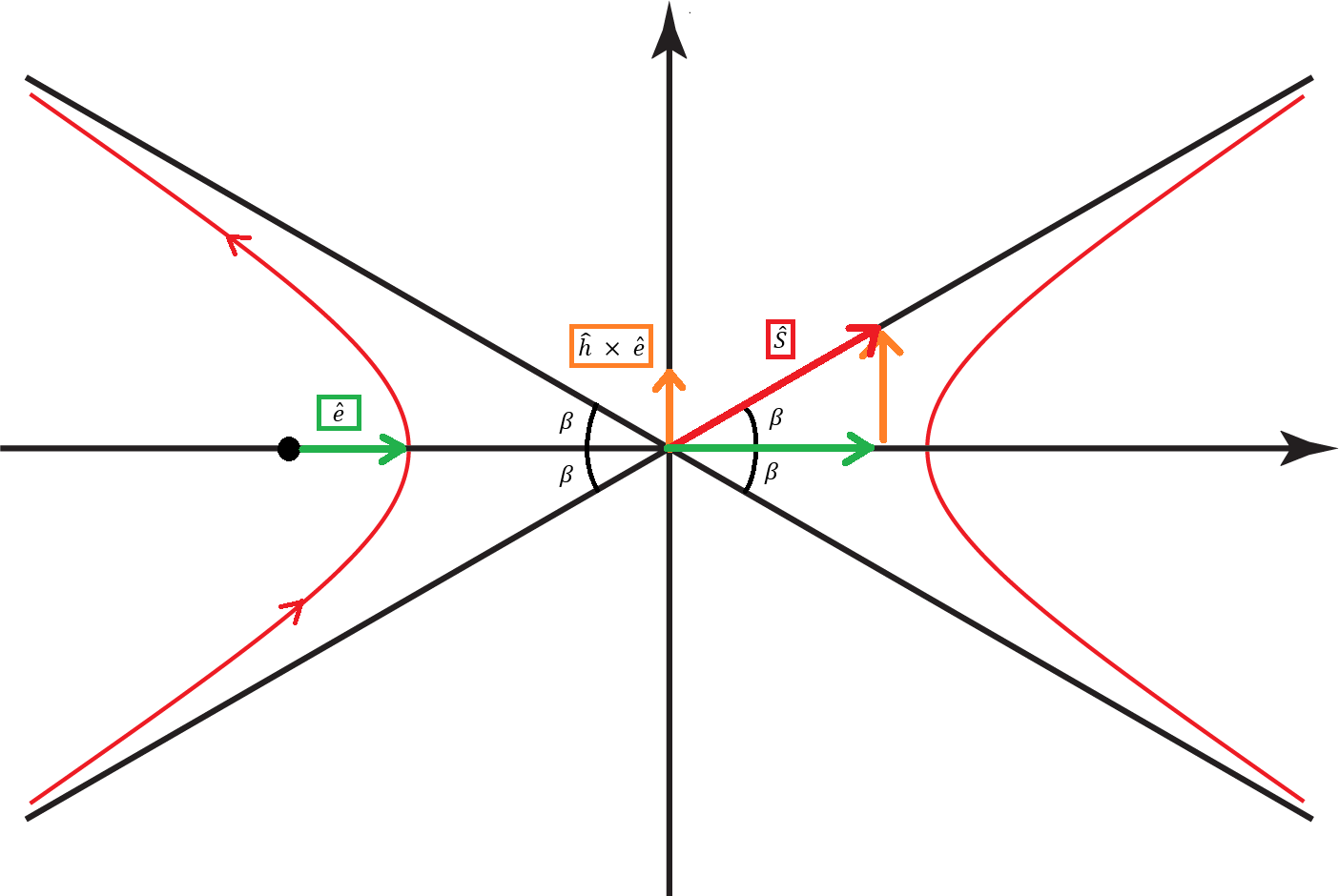
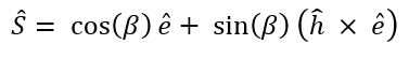
Next, we need to calculate the direction of the 'S' unit vector. Remember that the 'S' unit vector describes the direction of the entering asymptote. To derive the math for it, let's look at a plot of the hyperbolic plane.
Hyperbola Plot
We know that our 'S' unit vector is in the direction of the entering asymptote. We also know the half-angle, 'β' of the asymptotes. With this, we can break down the 'S' unit vector into two components - one in the 'e' unit vector direction, and one in the 'h x e' unit vector direction (the h vector is coming out of the page in this diagram). Doing so, we get this formula for the 'S' unit vector.
We still have two more unit vectors to solve for. Next, let's try to find the 'T' unit vector. If we define the 'N' unit vector as the direction of the z-axis of the reference frame, 'N' will be <0, 0, 1>. Then, we can find the 'T' unit vector.
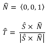
To complete the 'S' and 'T' unit vectors, we must now find the 'R' unit vector. This one is the cross product of the 'S' and 'T' unit vector.
![]()
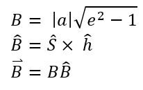
Now that we have our unit vectors, let's try to find what we've been looking all along: the 'B' vector and 'Θ'. To find the magnitude of the 'B' vector, we need the semi-major axis and the eccentricity of the hyperbolic trajectory. The magnitude of the 'B' vector can be found in the formula below. Once we have that, we need the direction of the 'B' vector. This should be the cross product of the 'S' unit vector' and the 'h' unit vector. Now that we have the magnitude and the unit vector, if we multiply them together, we will have our 'B' vector.
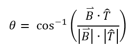
Our angle 'Θ' is simply the vertex angle of the 'B' vector and the 'T' unit vector. To calculate 'Θ', we use the following formula:
Modeling the B-Plane
Problem: A spacecraft has a state vector of <-299761, -440886, -308712> km and <1.343, 1.899, 1.329> km/s around Mars in the MJ2000 reference frame. Calculate the 'B' vector and 'Θ' for this spacecraft. |
Luckily, FreeFlyer already has tools built in to calculate these things for us. However for this Mission Plan, we will not only calculate these parameters, but visualize them as well.
•Create a New Mission Plan and save it as "BPlaneVisualization.MissionPlan"
Adding a Spacecraft
•Add a Spacecraft through the Object Browser
•Change the Spacecraft central body to "Mars"
•Give the Spacecraft the Cartesian elements given in the problem statement.
•In the Spacecraft's force model, make sure that Mars and the Sun are the only two bodies checked
•Click "Ok" to close the editor
Adding a Vector
•Create a Vector in the Object Browser
oRight-click the Object Browser
oAdd → Variables → Vector
•Rename this Vector to "B" by right-clicking the Vector and selecting "Rename"
•Create another Vector and name it "S"
•Create another Vector and name it "T"
•Create another Vector and name it "R"
Adding the ViewWindow
•Create a ViewWindow through the Object Browser
•Double-click "ViewWindow1" to open the editor
•Check "Spacecraft1" and all four Vector objects
•Check "Show Name" for all the objects
•Change the history mode to "Unlimited" for "Spacecraft1"
•Go into "Viewpoints" on the left-hand side of the editor
•Change the reference frame to "Inertial"
•Change the source, target, and tail reference to "Mars"
•Click "Ok" to close the editor
Building the Mission Sequence
•Drag and drop a FreeForm script editor onto the Mission Sequence
•Rename the script to "Calculate Vectors"
In this script, we will be using the formulas from Calculating the B-Plane to calculate the values of the Vector objects that we've created. To start off, we need to record the Spacecraft's state vector. To do this, we write:
// Initial state vector Array rVect = Spacecraft1.Position; Array vVect = Spacecraft1.Velocity; |
Next, we can start calculating the 'h' unit vector and the 'e' vector. One important thing to note is that ".Norm" will return the magnitude of the vector array and ".Normalized" will return the unit vector. When we calculate the 'h' unit vector, what we are asking for is the unit vector of the cross product of 'r' and 'v'. To calculate these values, we write:
// Calculations Array hUnit = rVect.CrossProduct(vVect).Normalized; Array eVect = (1/Mars.Mu) * (vVect.Norm^2 * rVect - (rVect.DotProduct(vVect)) * vVect) - rVect.Normalized; |
Next, we can calculate the angle 'β' and all of the other unit vectors. To do this, we write:
Variable beta = acos(1/eVect.Norm);
Array sUnit = cos(beta) * eVect.Normalized + sin(beta) * (hUnit.CrossProduct(eVect.Normalized)); Array nUnit = {0,0,1}; Array tUnit = sUnit.CrossProduct(nUnit).Normalized; Array rUnit = sUnit.CrossProduct(tUnit); |
Last, but not least, we need to calculate the 'B' vector. To do this, we need to first calculate the 'B' unit vector. Then we multiply the 'B' unit vector by the magnitude, which we can pull directly from Spacecraft1 to get the 'B' vector. Do to this, we write:
Array bUnit = sUnit.CrossProduct(hUnit); Variable bMag = Spacecraft1.BPlaneBMag(Mars);
Array bVect = bMag * bUnit; Variable bTheta = Spacecraft1.BPlaneTheta(Mars); |
Now that we have calculated all of the vectors, let's work on setting up the vectors
•Drag and drop a FreeForm script editor at the bottom of the Mission Sequence
•Rename the script to "Initialize Vectors"
In this script, we will be setting up our vectors. To do this, we will be matching the epochs, assigning the elements, building the vectors, changing the draw method, setting the colors, making them active, and offsetting the vectors so their origins lie in the center of Mars. To do this, we write:
// Set up the vector epochs B.Epoch = Spacecraft1.Epoch; S.Epoch = Spacecraft1.Epoch; T.Epoch = Spacecraft1.Epoch; R.Epoch = Spacecraft1.Epoch;
// Set up the vector elements B.Element = bVect; S.Element = sUnit; T.Element = tUnit; R.Element = rUnit;
// Build all the vectors B.BuildVector(0); S.BuildVector(0); T.BuildVector(0); R.BuildVector(0);
// Set to draw as arrows B.DrawMethod = 1; S.DrawMethod = 1; T.DrawMethod = 1; R.DrawMethod = 1;
// Set the vector colors B.Color = ColorTools.Yellow; S.Color = ColorTools.Red; T.Color = ColorTools.Cyan; R.Color = ColorTools.Green;
// Set all the vectors as visible B.Active = 1; S.Active = 1; T.Active = 1; R.Active = 1;
// Set the position of the vectors B.VisualOffset = Mars.GetPositionAtEpoch(Spacecraft1.Epoch) - Earth.GetPositionAtEpoch(Spacecraft1.Epoch); S.VisualOffset = Mars.GetPositionAtEpoch(Spacecraft1.Epoch) - Earth.GetPositionAtEpoch(Spacecraft1.Epoch); T.VisualOffset = Mars.GetPositionAtEpoch(Spacecraft1.Epoch) - Earth.GetPositionAtEpoch(Spacecraft1.Epoch); R.VisualOffset = Mars.GetPositionAtEpoch(Spacecraft1.Epoch) - Earth.GetPositionAtEpoch(Spacecraft1.Epoch); |
Let's move back to the Mission Sequence
•Drag and drop a while loop at the bottom of the Mission Sequence
•Change the while loop argument to "(Spacecraft1.ElapsedTime < TIMESPAN(6 days))"
•Drag and drop a FreeForm script editor inside the while loop
•Rename the script to "Step, Move, and Update"
In this script, we will step the Spacecraft, move the vectors so their origins rest at the center of Mars, and then update the ViewWindow. To do this, we write:
// Steps the spacecraft forward Step Spacecraft1;
// Moves the position of the vectors B.VisualOffset = Mars.GetPositionAtEpoch(Spacecraft1.Epoch) - Earth.GetPositionAtEpoch(Spacecraft1.Epoch); S.VisualOffset = Mars.GetPositionAtEpoch(Spacecraft1.Epoch) - Earth.GetPositionAtEpoch(Spacecraft1.Epoch); T.VisualOffset = Mars.GetPositionAtEpoch(Spacecraft1.Epoch) - Earth.GetPositionAtEpoch(Spacecraft1.Epoch); R.VisualOffset = Mars.GetPositionAtEpoch(Spacecraft1.Epoch) - Earth.GetPositionAtEpoch(Spacecraft1.Epoch);
// Updates the ViewWindow Update ViewWindow1; |
Lastly, let's report the 'B' vector, and angle.
•Drag and drop a FreeForm script editor at the bottom of the Mission Sequence
•Rename the script to "Report Calculations"
In this script, we will report the 'B' vector, and the angle. To do this, we write:
// Reports the B vector and angle Report bVect, bTheta; |
Your Mission Sequence should look something like this:
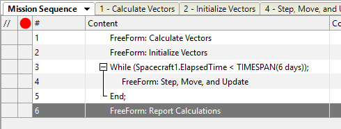
Sample Mission Sequence
Save and run your Mission Plan and try to answer the following questions:
What were the Cartesian elements of the 'B' vector?
What was the angle between the 'B' vector and the 'T' unit vector?
Try calculating the 'B' magnitude by hand. How does it compare to FreeFlyer's output?
We explained earlier that the 'B' vector points to where the Spacecraft would pierce the B-plane if it ignored the planet's gravity. Set 'B.DrawMethod' equal to 0 in the "Initialize Vectors" FreeForm and then turn off Mars's gravity in the Spacecraft Force Model. Run the Mission Plan again to check this claim.