In the Interplanetary Topics tutorial, we discussed how the B-plane can be used by mission planners to fly by a specific location on a planet, or target a capture orbit of a specific inclination. As a quick review, we recall that the B-plane is defined as orthogonal to the hyperbolic trajectory plane, and is described by three unit vectors R, S, and T, where S is parallel to the hyperbolic excess velocity, T lies on the ecliptic plane of the solar system, and R completes the right-handed set. R and T form the unit vectors of the B-plane itself.
We also define the B vector, which points from the center of the planetary body for which the B-plane is defined to the point at which the incoming asymptote of a spacecraft's hyperbolic trajectory pierces the B-plane. Finally, we define an angle Θ, which is the angle between the B vector and T vector.
For more information on what these vectors mean and how to calculate them, see The B-Plane in Interplanetary Topics. We will be reusing some methods from the aforementioned section for calculating and visualizing the B-plane in this tutorial.
The B-Plane in FreeFlyer
In the B-plane tutorial in the Interplanetary Topics chapter, we calculated the B-plane vectors manually in FreeFlyer in order to visualize them and develop an understanding of what they mean. However, FreeFlyer has the capability to calculate many of these parameters for us! We can use built-in methods to calculate where a spacecraft's hyperbolic trajectory pierces the B-plane. These methods are:
•BPlaneBMag - returns the distance of the piercing point from the origin of the B-plane (the center of the specified CelestialObject) [km]
•BPlaneTheta - returns the angle in the B-plane between the B and T vectors [deg]
•BPlaneBdotT - returns the projection of the piercing point onto the T vector [km]
•BPlaneBdotR - returns the projection of the piercing point onto the R vector [km]
We will use these methods to target a specific point on Mars's B-plane, a technique which is often used to achieve a desired orbit or flyby location.
Problem: Scientists want to investigate the presence of liquid water on Mars's polar ice caps. We have a spacecraft flying on a hyperbolic trajectory towards Mars. Using two impulsive burns, we want to insert the spacecraft into a circular, polar orbit to map the poles and gather scientific data. Use targeting loops to determine the magnitudes and components required of the burns to achieve our goal. |
This mission plan will include Targeting loops and B-plane configuration as well as a lot of visualization aspects for convenience. Although you should be sure to understand the code in the tutorial which applies to Targeting and the B-plane, feel free to skim over the visualization aspects, unless they are particularly interesting to you.
•Create a New Mission Plan and save it as "TargetingMarsBPlane.MissionPlan"
Adding Spacecraft Objects
•Create a new Spacecraft and change its Central Body to Mars
•Set the following orbital elements (remember to change the "Element Type" field to "Keplerian"):
oA: -6000 km
oE: 2
oI: 35 deg
oRAAN: 0 deg
oW: 0 deg
oTA: 243 deg
•In the "Force Model" tab, select the Mars checkbox under "Available Bodies". This will include Mars's gravity in the Spacecraft's Force Model
•Click "Ok" to close the Editor
•Create another new Spacecraft named "MarsCenter"
•Change the Spacecraft's Central Body to Mars
Note: This Spacecraft is being used solely to visualize the B-plane. It's position will be at the center of Mars, and it's Proximity Zones will represent the trajectory plane (of Spacecraft1) and Mars's B-plane. An understanding of Proximity Zones is NOT required for this tutorial.
•Navigate to the "Proximity Zones" tab (under "Subsystems"). We will create two Proximity Zones to visualize B-plane properties.
oClick "Create" to create your first Proximity Zone and give it the Name "TrajectoryPlane", then click "Edit ProximityZone"
oUnder "Size", set X = 20000 km, Y = 20000 km, and Z = 5 km
oUnder "Orientation wrt Reference Frame", set the "Offsets applied to" field to "Mean of Earth J2000", and set "Euler Angle 2" to 45
oNavigate to the "Visualization" tab and select "Translucent" (rather than "Wire Frame") and change the Tick Scale to 100000 km. Change the Color to a light blue (this step is not necessary, but recommended for consistency), and change the Opacity to 0.3
oClick "Ok" to close the Editor
oYour recently created Proximity Zone "TrajectoryPlane" should be selected. Click "Clone" to create an exact copy of this Proximity Zone, and rename it "BPlane", then click "Edit ProximityZone"
oThe current properties of the BPlane Proximity Zone are exact copies of the TrajectoryPlane Proximity Zone. Change "Euler Angle 2" to 0
oNavigate to the "Visualization" tab and change the Color to yellow (or another color which is different from the TrajectoryPlane color)
oThe Editor displays your Proximity Zones in a window. At this point, it should look something like this (you can zoom around within the window):
oNote that eventually, we will position the MarsCenter spacecraft so that it is at the center of Mars (as well as its associated Proximity Zones). We will do this later, in FreeFlyer script.
oClick "Ok" to close the Proximity Zone Editor
oClick "Ok" to close the Spacecraft Editor
Adding ImpulsiveBurn Objects
•Create a new ImpulsiveBurn object
•Open the ImpulsiveBurn editor
•Change the attitude system to "VNB"
•Click "Ok" to close the editor
•Repeat the process for a second ImpulsiveBurn object
Adding CoordinateSystem and Vector Objects
•Create a new CoordinateSystem Object and name it "BPlane" (You can right-click to Rename)
•Create five vector objects and name them "B", "R", "S", "T", and "X"
Adding ViewWindows
•Create a new ViewWindow Object
•Open the ViewWindow Editor
•Under "Available Objects", check Spacecraft1
•Change the history mode for Spacecraft1 to "Unlimited"
•Navigate to the "Viewpoints" tab
•Fill in the Default Viewpoint with the following properties:
oName: DistanceView
oTitle: DistanceView
oType: 3D View
oReference Frame: Inertial
oSource: Mars
oTarget: Mars
oTail Reference: Mars
oRight Ascension: 209 deg
oDeclination: -17 deg
oRadius: 309900 km
oField of View: 45 deg
•Click "Ok" to close the editor
•Create another ViewWindow Object
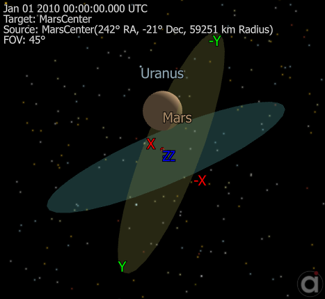
•Under "Available Objects", check Spacecraft1, MarsCenter, and Vectors B, R, S, and T
•Select Spacecraft1 and change the "History Mode" to "Unlimited"
•For Spacecraft1, B, R, S, and T, check the "Show Name" box
•Navigate to the "Viewpoints" tab
•Fill in the Default Viewpoint with the following properties:
oName: Default
oTitle: Default
oType: 3D View
oReference Frame: Inertial
oSource: Mars
oTarget: Mars
oTail Reference: Mars
oRight Ascension: 296 deg
oDeclination: -17 deg
oRadius: 30000 km
oField of View: 45 deg
•Click "Ok" to close the editor
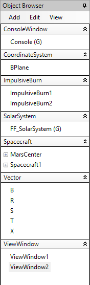
At this point, your Object Browser should look something like this:
Now we are ready to begin writing our Mission Sequence. Since this Mission Plan is fairly complicated, we will be using FreeFlyer script in the FreeForm script editor rather than the "drag-and-drop" method to execute our commands. Using Freeflyer script provides more flexibility and allows you to access more Properties of Objects than you could otherwise. In instances where the script is outside the scope of this tutorial (such as for visualization purposes), we will suggest that you copy and paste the example code provided.
Setting up the Console
•Drag and drop a FreeForm script editor into the Mission Sequence, and double click to open it
•Rename the FreeForm "Set up Console"
•Copy and paste the following code into the FreeForm script editor (this will simply set up the Console window for convenient reports at various times in the mission, and display Mars with a SurfaceLayer)
Console.BackColor = ColorTools.Black; Console.DockMode = 3; Console.Dimension = 50; Console.CurrentTextColor = ColorTools.Lime; Console.WordWrap = 1; Console.Show();
// Set up Mars visualization Mars.Globe.SurfaceLayer.UseDaytimeImage = 1; |
Targeting the B-Plane
•Go back to the Mission Sequence
•Drag and drop another FreeForm script editor at the bottom of the Mission Sequence
•Rename this FreeForm to "Target B-Plane at Mars's South Pole"
In this script, we will implement our first Targeting loop, to intersect Mars's B-plane at a radius of 8000 km and angle theta of 115 degrees (we use 115 because Mars has an axial tilt of 25 degrees - if there were no tilt, we would want to intersect the B-plane at an angle of 90 degrees to achieve a polar orbit).
First, we will report the current action to the Console and save the Spacecraft's initial state so that we can retrieve it later. We will also change the spacecraft's color for visualization purposes, and increase the StepSize to make the simulation run faster. Finally, we will create a variable called "peri_time" to store the time that the spacecraft will reach periapsis - this is useful so that we can propagate the orbit within the targeting loop and see the actual targeting process. To do this, copy and paste the following code into the FreeForm script editor:
// Update the Console on what is happening Console.CurrentTextColor = ColorTools.Aqua; Report "Targeting the B-Plane at Mars's south pole..." to Console; Report "" to Console;
// Save the Spacecraft's current state so that we can go back and propagate from the beginning Save Spacecraft1 as "initial state";
// Set the Spacecraft color Spacecraft1.Color = ColorTools.Aqua;
// Increase the step size to speed up simulation Spacecraft1.Propagator.StepSize = TIMESPAN(500 seconds); |
Next, we will create the Targeting loop by typing:
Target;
End; |
The next portions of our code will exist inside of the Targeting loop (before the "End" statement). Try to construct the Targeting loop yourself by following the instructions! Example code is included after the instructions for reference.
•The commands that you will need to use are
o"Iterate" - indicates to the loop which objects to restore to their initial properties at each iteration
o"Vary" - indicates which objects to change at each iteration, requires a seed and perturbation (i.e. "Vary ObjectName = seed + perturbation;")
o"Maneuver" - applies the ImpulsiveBurn to the Spacecraft
o"Achieve" - indicates the goals of the targeting loop, as well as their tolerances (i.e. "Achieve ObjectName = goal +/- tolerance;")
•Use the Iterate command to tell the Targeting loop to restore Spacecraft1 after each iteration
•Vary all three directions (V, N, and B) of ImpulsiveBurn1, accessed through the BurnDirection property (ImpulsiveBurn1.BurnDirection[0] is the first direction, V. Use indices 1 and 2 to access the N and B directions). Use a seed value of 0.1 km/s and a perturbation of 0.001 km/s for all three directions
•Use the Maneuver command to apply an impulsive Δv to Spacecraft1 using ImpulsiveBurn1
•Achieve a B-plane magnitude of 8000 km with a tolerance of 5 km, and an angle of 115 degrees with a tolerance of 0.5 degrees (recall the B-plane methods in FreeFlyer that we discussed earlier!)
oWe must target an angle of 115 degrees for a polar orbit because Mars has an axial tilt of 25 degrees, and the T vector points along the ecliptic plane, so we must account for the tilt in our targeting
•After you have attempted to construct the Targeting loop on your own, check your code against the following:
Target;
Iterate Spacecraft1;
// Allow all three burn direction magnitudes to vary Vary ImpulsiveBurn1.BurnDirection[0] = 0.1 + 0.001; Vary ImpulsiveBurn1.BurnDirection[1] = 0.1 + 0.001; Vary ImpulsiveBurn1.BurnDirection[2] = 0.1 + 0.001;
// Perform the calculated maneuver Maneuver Spacecraft1 using ImpulsiveBurn1;
// Attempt to achieve a B vector magnitude of 8000 km and an angle between B and T of 115 degrees Achieve Spacecraft1.BPlaneBMag(Mars) = 8000 +/- 5; Achieve Spacecraft1.BPlaneTheta(Mars) = (90+25) +/- 0.5;
End; |
For this tutorial, it will be useful to visualize the targeting process. To do this, we will update the ViewWindow while stepping the Spacecraft to the periapsis of the orbit created by maneuvering using ImpulsiveBurn1. By doing this inside of the Targeting loop, we can visualize the resulting orbit from each iteration of the Targeter. Inside of the Targeting loop (but after the Achieve statements), write:
// Propagate to periapsis WhileStepping Spacecraft1 to (Spacecraft1.OrbitPeriapsis); Update ViewWindow1; End;
ViewWindow1.InsertLineBreak(); |
Our Targeting loop is now complete! The final step is to restore the Spacecraft to its initial state, which we do after the end of the Targeting loop by typing:
Restore Spacecraft1 from "initial state"; |
Double check that your code (from the beginning of the Targeting loop) looks like this:
Target;
Iterate Spacecraft1;
// Allow all three burn direction magnitudes to vary Vary ImpulsiveBurn1.BurnDirection[0] = 0.1 + 0.001; Vary ImpulsiveBurn1.BurnDirection[1] = 0.1 + 0.001; Vary ImpulsiveBurn1.BurnDirection[2] = 0.1 + 0.001;
// Perform the calculated maneuver Maneuver Spacecraft1 using ImpulsiveBurn1;
// Attempt to achieve a B vector magnitude of 8000 km and an angle between B and T of 115 degrees Achieve Spacecraft1.BPlaneBMag(Mars) = 8000 +/- 5; Achieve Spacecraft1.BPlaneTheta(Mars) = (90+25) +/- 0.5;
// Propagate to periapsis WhileStepping Spacecraft1 to (Spacecraft1.OrbitPeriapsis); Update ViewWindow1; End;
ViewWindow1.InsertLineBreak();
End;
Restore Spacecraft1 from "initial state"; |
We are now finished with our first Targeting loop! If you'd like, you can save and run your Mission Plan at this point to see how the Spacecraft's trajectory changes with each iteration of the Targeter. If you do run your Mission Plan, you should see something like this:
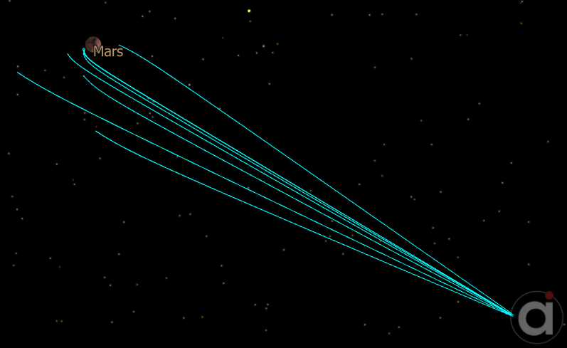
When the simulation runs on your screen, you should be able to see how the trajectory changes and approaches the goal each time the Targeter varies the magnitude of various components of the initial burn. Click "Control" at the top of the screen to return to your script.
Resetting the View and Propagating the Converged Solution Trajectory
•Go back to the Mission Sequence
•Drag and drop another FreeForm script editor at the bottom of the Mission Sequence
•Rename this FreeForm to "Reset Viewpoint"
This script is mostly for visualization purposes. We will clear all the iterations of the Targeter from the ViewWindow and adjust the viewpoint so that we can zoom along with the spacecraft as it approaches Mars on the trajectory determined by the Targeting loop. We will propagate this solution from the start to the point of periapsis, at which point we will enter our second Targeting loop (in the next section). Copy and paste the example code below into your FreeForm:
// Clear targeting tails ViewWindow1.ResetTails(); Spacecraft1.Color = ColorTools.Aqua; Spacecraft1.Propagator.StepSize = TIMESPAN(50 seconds); // Slow the simulation down
// Apply the ImpulsiveBurn determined by the Targeter Maneuver Spacecraft1 using ImpulsiveBurn1; Save Spacecraft1 as "temp_save"; Step Spacecraft1 to (Spacecraft1.OrbitPeriapsis(Mars)); periEpoch = Spacecraft1.Epoch; // Save time of periapsis Restore Spacecraft1 from "temp_save";
// Count the number of steps to determine the zoom rate Variable count = 0; WhileStepping Spacecraft1 to (Spacecraft1.OrbitPeriapsis); count += 1; End; Restore Spacecraft1 from "temp_save";
// Zoom in with the Spacecraft ViewWindow1.SetShowName(Spacecraft1.ObjectId, 1); ViewWindow1.CurrentViewpoint.ThreeDView.RightAscension = 236; ViewWindow1.CurrentViewpoint.ThreeDView.Declination = -29; Variable deltaRA = abs(209-236)/count; Variable deltaDec = abs((-17) - (-29))/count; Variable deltaZoom = (309900 - 30000)/count; Variable i = 1;
WhileStepping Spacecraft1 to (Spacecraft1.OrbitPeriapsis); ViewWindow1.CurrentViewpoint.ThreeDView.Radius = 309900-(deltaZoom*i); ViewWindow1.CurrentViewpoint.ThreeDView.RightAscension = 236 - (deltaRA*i); ViewWindow1.CurrentViewpoint.ThreeDView.Declination = -29 + (deltaDec*i); Update ViewWindow1; i += 1; End;
// Now, the spacecraft should be at periapsis |
Targeting a Circular, Polar Orbit
•Go back to the Mission Sequence
•Drag and drop another FreeForm script editor at the bottom of the Mission Sequence
•Rename this FreeForm to "Target a circular polar orbit"
Here, we will use another Targeting loop to insert our spacecraft into a circular orbit. First, we will report the current action to the Console. Then, we need to step the Spacecraft to exactly the time of periapsis - although we used a While loop to step it to periapsis in the previous section, our Spacecraft's StepSize property may not have allowed the Spacecraft to step to the exactly correct time, so it is a good practice to use a "Step to" command to ensure we have everything set up correctly. Copy and paste the following code into the FreeForm script editor:
// Update the Console on what is happening Console.CurrentTextColor = ColorTools.Yellow; Report "Targeting a circular orbit..." to Console; Report "" to Console;
// Change Spacecraft Color Spacecraft1.Color = ColorTools.Yellow; Update ViewWindow1; |
We are now ready to create our second Targeting loop. Try using what you learned from the first targeting loop to construct this one yourself!
•Use the Iterate command to tell the Targeting loop to restore Spacecraft1 after each iteration
•Vary just the first component of ImpulsiveBurn2 (the V component) with a seed of -2 km/s and a perturbation of 0.001 km/s
•Use the Maneuver command to apply an impulsive Δv to Spacecraft1 using ImpulsiveBurn2
•Achieve an eccentricity for Spacecraft 1 of 0 with a tolerance of 0.0001
The targeting aspect of the loop is now complete, but again we would like to visualize how the Targeter works to refine the solution to a circular orbit. To do this, we will step Spacecraft1 for a full period of its (now elliptical) orbit for each iteration. Copy and paste the following code inside your Targeting loop:
// Visualize the solution from each iteration of the targeting loop
Step Spacecraft1; // Must step so that we are not already at periapsis Update ViewWindow1;
WhileStepping Spacecraft1 to (Spacecraft1.OrbitPeriapsis); Update ViewWindow1; End;
ViewWindow1.InsertLineBreak(); |
Finally, restore the Spacecraft to its initial state after the end of the Targeting loop by typing:
Restore Spacecraft1 from "initial state"; |
Your code (from the beginning of the Targeting loop) should look like this:
Target;
Iterate Spacecraft1;
// Vary just the burn in the velocity direction Vary ImpulsiveBurn2.BurnDirection[0] = -2 + 0.001;
// Perform the calculated maneuver Maneuver Spacecraft1 using ImpulsiveBurn2;
// Achieve a circular orbit Achieve Spacecraft1.E = 0 +/- 0.0001;
// Visualize the solution for each iteration of the targeting loop Step Spacecraft1; Update ViewWindow1;
WhileStepping Spacecraft1 to (Spacecraft1.OrbitPeriapsis); Update ViewWindow1; End;
ViewWindow1.InsertLineBreak();
End;
// Restore the Spacecraft to its beginning state Restore Spacecraft1 from "initial state"; |
If you'd like, you can save and run your Mission Plan at this point to see how the Spacecraft's trajectory changes with each iteration of the Targeter. If you do run your Mission Plan, you should have something like this at the end:
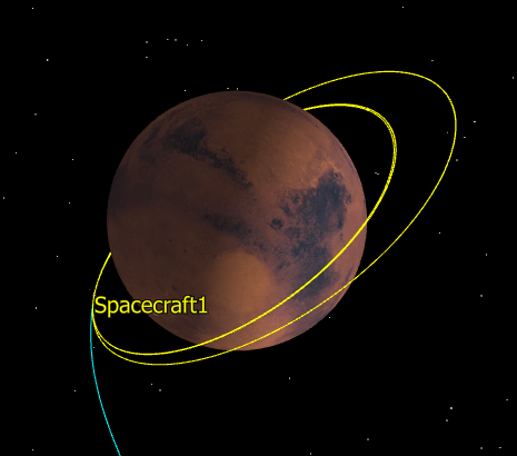
When the simulation runs on your screen, you should first see the iterations of the first targeting loop that you wrote (in light blue), then you should zoom in to a closer view to see the solution trajectory produced by the first ImpulsiveBurn, then the iterations of the second targeting loop that you wrote (in yellow). We now have solutions for the two burns! All that is left is to visualize the B-plane and view the final trajectory. Click "Control" at the top of the screen to return to your script.
Visualizing the B-Plane
•Go back to the Mission Sequence
•Drag and drop another FreeForm script editor at the bottom of the Mission Sequence
•Rename this FreeForm to "Visualize B-Plane"
Much of this script comes from the earlier tutorial The B-Plane in the Interplanetary Topics chapter. Refer to that section if you would like to review B-plane concepts. Copy and paste the following code into the FreeForm script editor:
Maneuver Spacecraft1 using ImpulsiveBurn1;
// Initial state vector Array rVect = Spacecraft1.Position; Array vVect = Spacecraft1.Velocity;
// Calculations Array hUnit = rVect.CrossProduct(vVect).Normalized; Array eVect = (1/Mars.Mu) * (vVect.Norm^2 * rVect - (rVect.DotProduct(vVect)) * vVect) - rVect.Normalized;
Variable beta = acos(1/eVect.Norm);
Array sUnit = cos(beta) * eVect.Normalized + sin(beta) * (hUnit.CrossProduct(eVect.Normalized)); Array nUnit = {0,0,1}; Array tUnit = sUnit.CrossProduct(nUnit).Normalized; Array rUnit = sUnit.CrossProduct(tUnit);
Array bUnit = sUnit.CrossProduct(hUnit); Variable bMag = Spacecraft1.BPlaneBMag(Mars);
Array bVect = bMag * bUnit; Variable bTheta = Spacecraft1.BPlaneTheta(Mars);
// Set up the vector epochs B.Epoch = Spacecraft1.Epoch; S.Epoch = Spacecraft1.Epoch; T.Epoch = Spacecraft1.Epoch; R.Epoch = Spacecraft1.Epoch;
// Set up the vector elements B.Element = bVect; S.Element = sUnit; T.Element = tUnit; R.Element = rUnit;
// Build all the vectors B.BuildVector(0); S.BuildVector(0); T.BuildVector(0); R.BuildVector(0);
// Set to draw as arrows B.DrawMethod = 1; S.DrawMethod = 1; T.DrawMethod = 1; R.DrawMethod = 1;
// Set the vector colors B.Color = ColorTools.Yellow; S.Color = ColorTools.Red; T.Color = ColorTools.Cyan; R.Color = ColorTools.Green;
// Set all the vectors as visible B.Active = 1; S.Active = 1; T.Active = 1; R.Active = 1;
// Set the position of the vectors B.VisualOffset = Mars.GetPositionAtEpoch(Spacecraft1.Epoch) - Earth.GetPositionAtEpoch(Spacecraft1.Epoch); S.VisualOffset = Mars.GetPositionAtEpoch(Spacecraft1.Epoch) - Earth.GetPositionAtEpoch(Spacecraft1.Epoch); T.VisualOffset = Mars.GetPositionAtEpoch(Spacecraft1.Epoch) - Earth.GetPositionAtEpoch(Spacecraft1.Epoch); R.VisualOffset = Mars.GetPositionAtEpoch(Spacecraft1.Epoch) - Earth.GetPositionAtEpoch(Spacecraft1.Epoch);
X.Element = {1000, 0, 0};
Restore Spacecraft1 from "initial state"; |
Propagating the Solution Trajectory
•Go back to the Mission Sequence
•Drag and drop another FreeForm script editor at the bottom of the Mission Sequence
•Rename this FreeForm to "Propagate Spacecraft"
Here, we will propagate and visualize the final solution trajectory of our Spacecraft, executing the two burns determined by our Targeting loops. First, we will report the current action to the Console and set up some visualization aspects. Copy and paste the following code into the FreeForm script editor:
// Update the Console on what is happening Console.CurrentTextColor = ColorTools.Magenta; Report "Propagating the Spacecraft's final trajectory..." to Console; Report "" to Console;
Spacecraft1.Color = ColorTools.Magenta; Spacecraft1.Propagator.StepSize = TIMESPAN(50 seconds);
// Set up View deltaZoom = (377800-54000)/count; i = 1; OutputLayout.SetWindowState(ViewWindow1.ID, 1); OutputLayout.SetWindowState(ViewWindow2.ID, 2); OutputLayout.ApplyUpdates(); Update ViewWindow2; |
Next, we will begin our actual propagation. First, we maneuver Spacecraft1 using ImpulsiveBurn1. Then, we will propagate the Spacecraft until it reaches periapsis, updating the B-plane and our ViewWindow each step of the way. Copy and paste the following code into the FreeForm script editor:
Maneuver Spacecraft1 using ImpulsiveBurn1;
// Propagate the spacecraft until it reaches periapsis WhileStepping Spacecraft1 to (Spacecraft1.OrbitPeriapsis);
// Set the MarsCenter Spacecraft at the center of Mars MarsCenter.Epoch = Spacecraft1.Epoch; MarsCenter.Position = {0, 0, 0};
// The TrajectoryPlane ProximityZone visualizes the orbit plane MarsCenter.ProximityZones[0].Orientation[0] = Spacecraft1.RAAN; MarsCenter.ProximityZones[0].Orientation[1] = Spacecraft1.I;
// The BPlane ProximityZone visualizes the B-Plane BPlane.Epoch = Spacecraft1.Epoch; BPlane.BuildCoordinateSystem(3, S, 1, X); MarsCenter.ProximityZones[1].SetOrientation(BPlane);
// Moves the position of the vectors B.VisualOffset = Mars.GetPositionAtEpoch(Spacecraft1.Epoch) - Earth.GetPositionAtEpoch(Spacecraft1.Epoch); S.VisualOffset = Mars.GetPositionAtEpoch(Spacecraft1.Epoch) - Earth.GetPositionAtEpoch(Spacecraft1.Epoch); T.VisualOffset = Mars.GetPositionAtEpoch(Spacecraft1.Epoch) - Earth.GetPositionAtEpoch(Spacecraft1.Epoch); R.VisualOffset = Mars.GetPositionAtEpoch(Spacecraft1.Epoch) - Earth.GetPositionAtEpoch(Spacecraft1.Epoch);
// Zoom in closer to Mars ViewWindow2.CurrentViewpoint.ThreeDView.Radius = 377800 - (deltaZoom*i); i += 1;
Update ViewWindow2; End; |
Now, we can move on to the second piece of the trajectory: insertion into a circular, polar orbit. Now that the Spacecraft has been stepped to periapsis, we will maneuver the Spacecraft using ImpulsiveBurn2. Finally, we will propagate the Spacecraft for half a day in its new circular orbit, continuing to update the B-plane and our ViewWindow. Copy and paste the following code into the FreeForm script editor:
// Perform the second Maneuver Maneuver Spacecraft1 using ImpulsiveBurn2;
// Propagate the spacecraft in its circular polar orbit for half a day While (Spacecraft1.ElapsedTime < TIMESPAN(0.5 days)); Step Spacecraft1;
// Set the MarsCenter Spacecraft at the center of Mars MarsCenter.Epoch = Spacecraft1.Epoch; MarsCenter.Position = {0, 0, 0};
// The TrajectoryPlane ProximityZone visualizes the orbit plane MarsCenter.ProximityZones[0].Orientation[0] = Spacecraft1.RAAN; MarsCenter.ProximityZones[0].Orientation[1] = Spacecraft1.I;
// The BPlane ProximityZone visualizes the B-Plane BPlane.Epoch = Spacecraft1.Epoch; BPlane.BuildCoordinateSystem(3, S, 1, X); MarsCenter.ProximityZones[1].SetOrientation(BPlane);
// Moves the position of the vectors B.VisualOffset = Mars.GetPositionAtEpoch(Spacecraft1.Epoch) - Earth.GetPositionAtEpoch(Spacecraft1.Epoch); S.VisualOffset = Mars.GetPositionAtEpoch(Spacecraft1.Epoch) - Earth.GetPositionAtEpoch(Spacecraft1.Epoch); T.VisualOffset = Mars.GetPositionAtEpoch(Spacecraft1.Epoch) - Earth.GetPositionAtEpoch(Spacecraft1.Epoch); R.VisualOffset = Mars.GetPositionAtEpoch(Spacecraft1.Epoch) - Earth.GetPositionAtEpoch(Spacecraft1.Epoch);
Update ViewWindow2; End; |
Spacecraft1 has now completed its full targeted trajectory! The remaining code simply sets up the ViewWindows in a convenient way, then reports relevant information to the Console, including the targeted components of both burns, the B-plane properties, and the Spacecraft's final orbital properties. Copy and paste the following code into the FreeForm script editor:
OutputLayout.SetWindowState(ViewWindow1.ID, 0); OutputLayout.ArrangeWindows(0, {ViewWindow1.ID, ViewWindow2.ID}); OutputLayout.ApplyUpdates();
// Output relevant information Console.CurrentTextColor = ColorTools.Lime;
Report "First burn: " to Console; Report " V: ", ImpulsiveBurn1.BurnDirection[0] to Console; Report " N: ", ImpulsiveBurn1.BurnDirection[1] to Console; Report " B: ", ImpulsiveBurn1.BurnDirection[2] to Console; Report "" to Console;
Report "Second burn: " to Console; Report " V: ", ImpulsiveBurn2.BurnDirection[0] to Console; Report " N: ", ImpulsiveBurn2.BurnDirection[1] to Console; Report " B: ", ImpulsiveBurn2.BurnDirection[2] to Console; Report "" to Console;
Report "Angle between B and T: ", bTheta to Console; Report "Magnitude of B vector at initial piercing point: ", bMag to Console; Report "Final eccentricity: ", Spacecraft1.E to Console; Report "" to Console; |
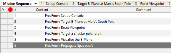
Go back to the Mission Sequence. You should have six FreeForm blocks like this:
Save and run your Mission Plan. You should see a simulation of targeting the first and second burns, then a new window depicting the final trajectory and visualizing the trajectory plane and B-plane. When the run finishes, you should have two windows side by side, one showing the end of the second targeting sequence (on the left) and the other showing the final trajectory (on the right). Use your mouse to zoom in and pan around both views. Notice how the trajectory plane in blue aligns perfectly with the Spacecraft's hyperbolic trajectory, and how the B-plane in yellow is exactly perpendicular to the trajectory plane. Also notice how the Spacecraft passes directly over both poles - you should be able to see Mars's polar ice caps. After examining your results, try to answer these questions:
The Console window should have reported the angle between B and T, as well as the magnitude of the B vector. Are they within the tolerances that we set for our goals in the first Targeting loop? In the final trajectory view, does the angle between B and T look like it could be 115 degrees, as we expect?
Why do we only need to burn in the V direction for the second impulsive burn? Try varying the other directions as well in the second Targeting loop, using a seed value of 0 km/s. Do they make a significant contribution to the total Δv if we allow them to vary?